ProcessMaster FEP610, HygienicMaster FEH610 | OI/FEP610/FEH610-EN Rev. B 29
Transmitter
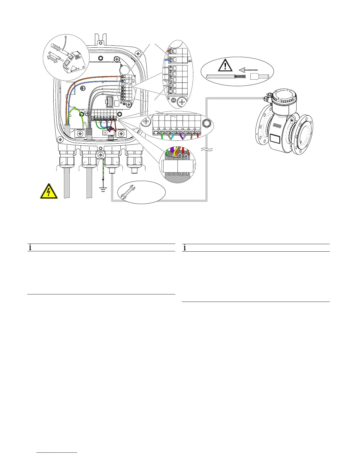
Fig. 42: Connection to transmitter in remote mount design (example)
1 Terminals for power supply 3 Terminal for signal cable 3 Terminals for inputs and outputs 4 Cable entry for inputs and outputs
5 Cable entry for signal cable 6 Terminal for potential equalization 7 Cable entry for power supply
Change from one to tw o columns
NOTE
If the O-ring gasket is seated incorrectly or damaged,
this may have an adverse effect on the housing
protection class.
Follow the instructions in chapter "Opening and closing the
terminal box" on page 18 to open and close the housing
safely.
Observe the following points when connecting to an electrical
supply:
— Lead the cable for the power supply and the signal inputs
and outputs into the housing as shown.
— Connect the cables in accordance with the electrical
connection diagram. If present, connect the cable
shielding to the earthing clamp provided.
— Use wire end ferrules when connecting.
— Close unused cable entries using suitable plugs.
NOTE
— Observe the power supply limit values in accordance
with the information on the name plate.
— Observe the voltage drop for large cable lengths and
small conductor cross-sections. The voltage at the
terminals of the device may not fall below the minimum
value required in accordance with the information on the
name plate.
The power supply is connected to terminal L (phase),
N (neutral), or 1+, 2-, and PE, as stated on the name plate.
A circuit breaker with a maximum rated current of 16 A must
be installed in the power supply line of the transmitter.
The wire cross-sectional area of the power supply cable and
the circuit breaker used must comply with VDE 0100 and must
be dimensioned in accordance with the current consumption
of the flowmeter measuring system. The cables must comply
with IEC 227 and/or IEC 245.
The circuit breaker should be located near the transmitter and
marked as being associated with the device.
Connect the transmitter and sensor to functional earth.
Change from two to one column
G12028
100 ... 240 V AC
24 ... 48 V DC
4 ... 20 mA
DO1 + DO2
3
S2 E2 E1 S1M1M2
PE
1+ L
2- N
31
32
41
42/52
51
M 20 mm /
NPT 1/2"
1
2
3
7 4
456
FE