Automatic voltage control for a single transformer
SEMOD159053-73 v6
Automatic voltage control for tap changer, single control TR1A
TCC (90) measures the
magnitude of the busbar voltage V
B
. If no other additional features are enabled (line
voltage drop compensation), this voltage is further used for voltage regulation.
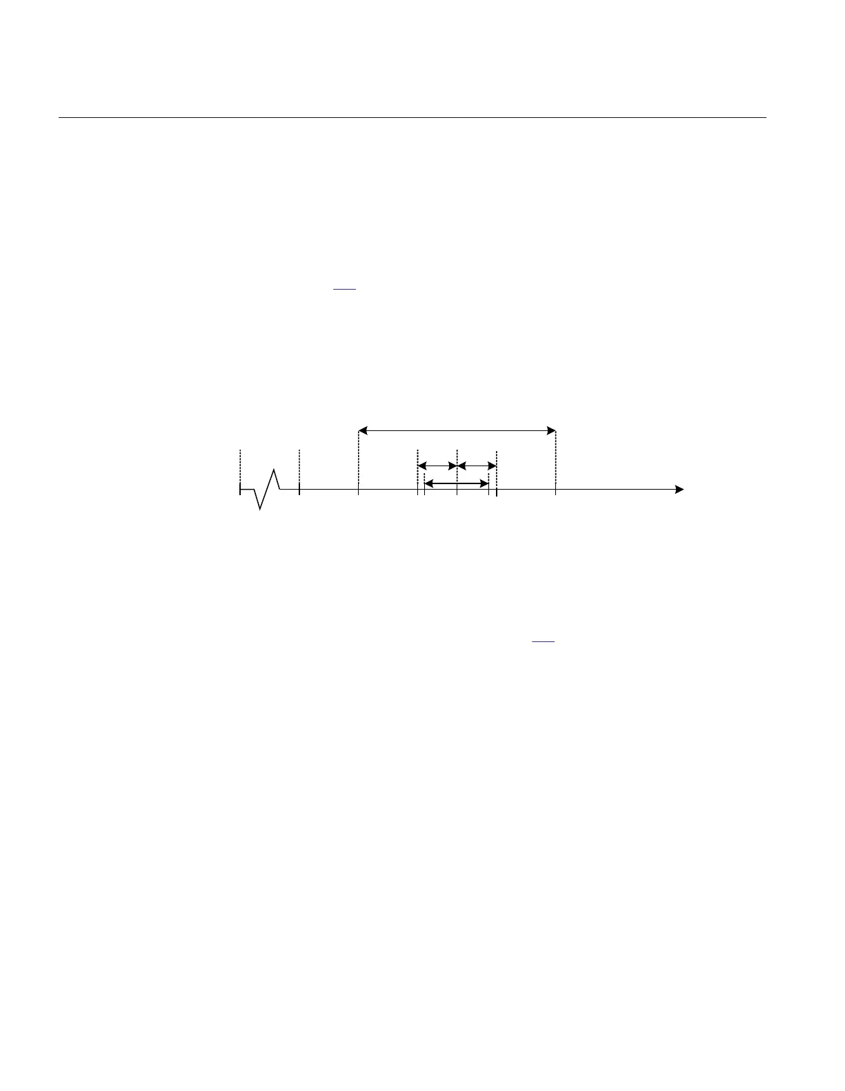
TR1ATCC (90) then compares this voltage with the set voltage, VSet and decides
which action should be taken. To avoid unnecessary switching around the setpoint, a
deadband (degree of insensitivity) is introduced. The deadband is symmetrical around
VSet, see figure
170, and it is arranged in such a way that there is an outer and an inner
deadband. Measured voltages outside the outer deadband start the timer to initiate tap
commands, whilst the sequence resets when the measured voltage is once again back
inside the inner deadband. One half of the outer deadband is denoted ΔV. The setting
of
ΔV, setting Vdeadband should be set to a value near to the power transformer’s tap
changer voltage step (typically 75–125% of the tap changer step).
Voltage MagnitudeVmax
V
2
VsetV
1
VminVblock0
Raise Cmd
*) Action in accordance with setting
Security Range
Lower Cmd
ANSI06000489-2-en.vsd
DD V V
DV
in
DV
in
*) *) *)
ANSI06000489 V2 EN-US
Figure 170: Control actions on a voltage scale
During normal operating conditions the busbar voltage V
B
, stays within the outer
deadband (interval between V1 and V2 in figure
170). In that case no actions will be
taken by TR1A
TCC (90). However, if V
B
becomes smaller than V1, or greater than
V2, an appropriate raise or lower timer will start. The timer will run as long as the
measured voltage stays outside the inner deadband. If this condition persists longer
than the preset time delay, TR1ATCC (90) will initiate that the appropriate VLOWER
or VRAISE command will be sent from TCMYLTC or TCLYLTC function block to
the transformer tap changer. If necessary, the procedure will be repeated until the
magnitude of the busbar voltage again falls within the inner deadband. One half of the
inner deadband is denoted ΔV
in
. The inner deadband ΔV
in
, setting VDeadbandInner
should be set to a value smaller than ΔV. It is recommended to set the inner deadband
to 25-70% of the ΔV value.
This way of working is used by TR1ATCC (90) while the busbar voltage is within the
security range defined by settings Vmin and Vmax.
A situation where V
B
falls outside this range will be regarded as an abnormal situation.
Section 14 1MRK 511 401-UUS A
Control
412 Bay control REC670 2.2 ANSI
Application manual

 Loading...


