Measurement function application for a 380kV OHL
SEMOD54481-12 v11
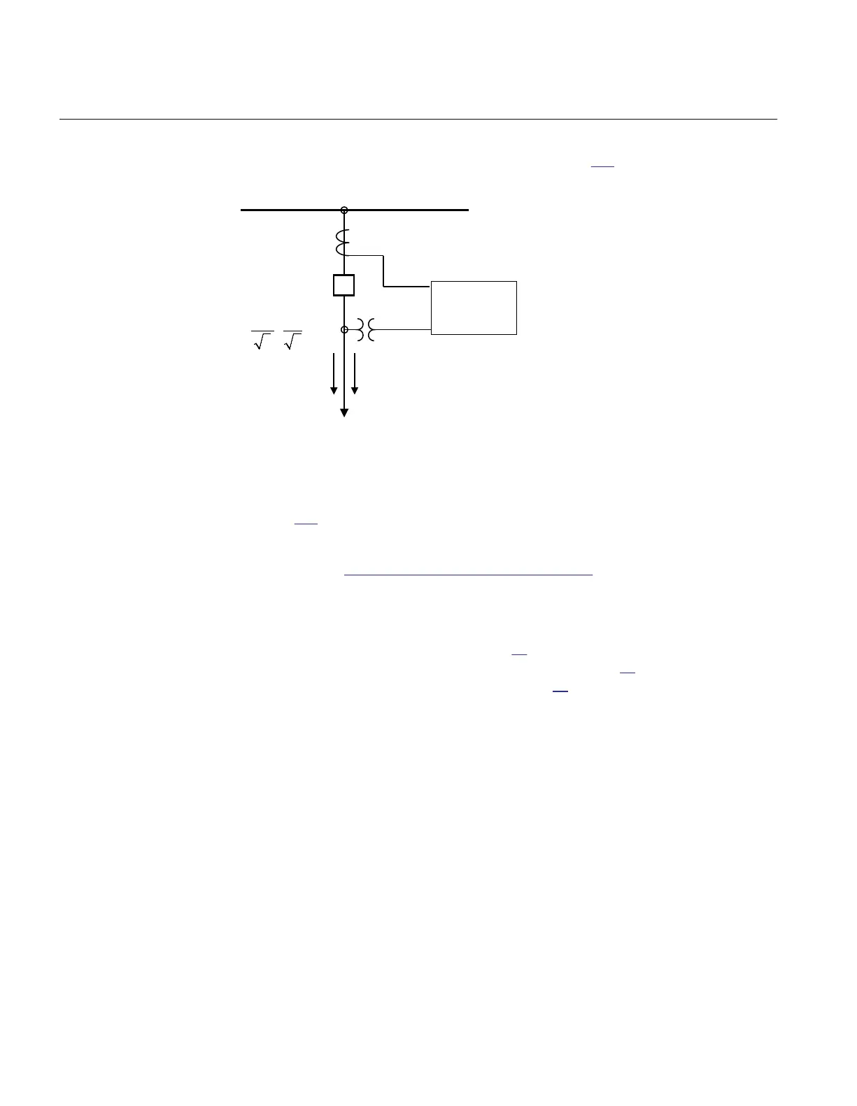
Single line diagram for this application is given in figure 207:
380kV Busbar
380kV OHL
P Q
800/5 A
ANSI09000039-1-en.vsd
380kV 120V
/
3 3
kV
IED
ANSI09000039 V1 EN-US
Figure 207: Single line diagram for 380kV OHL application
In order to monitor, supervise and calibrate the active and reactive power as indicated
in figure
207 it is necessary to do the following:
1. Set correctly CT and VT data and phase angle reference channel PhaseAngleRef
(see Section “Setting of the phase reference channel”) using PCM600 for analog
input channels
2. Connect, in PCM600, measurement function to three-phase CT and VT inputs
3.
Set under General settings parameters for the Measurement function:
• general settings as shown in table
46.
• level supervision of active power as shown in table 47.
• calibration parameters as shown in table 48.
Section 17 1MRK 511 401-UUS A
Monitoring
516 Bay control REC670 2.2 ANSI
Application manual

 Loading...


