-0.8 -0.6 -0.4 -0.2 0 0.2 0.4 0.6 0.8 1
-0.6
-0.4
-0.2
0
0.2
0.4
0.6
-
-
-
-
-
-
-
-
-
-
-
-
-
-
-
-
-
-
-
-
-
-
-
-
-
-
-
-
-
-
-
-
-
-
-
-
-
-
-
-
-
-
-
-
-
-
-
-
-
-
-
-
-
-
-
-
-
-
-
-
-
-
-
-
-
-
-
-
-
-
-
-
-
-
-
-
-
-
-
-
-
-
-
-
-
-
-
-
-
-
-
-
-
-
-
-
-
-
-
-
-
-
-
-
-
-
-
-
-
-
-
-
-
-
-
-
-
-
-
-
Real part (R) of Z in Ohms
Imaginary part (X) of Z in Ohms
^
^
^
^
^
^
^
^
^
^
^
^
^
^
^
^
^
^
-
-
-
-
-
-
-
-
-
-
-
-
-
-
-
-
-
-
-
-
-
-
-
-
-
-
-
-
-
-
- -
-
-
-
-
-
-
-
-
-
-
-
-
-
-
-
-
-
-
-
-
-
-
-
-
-
-
-
-
-
-
Ztr
Ze
Zgen
SE
RE
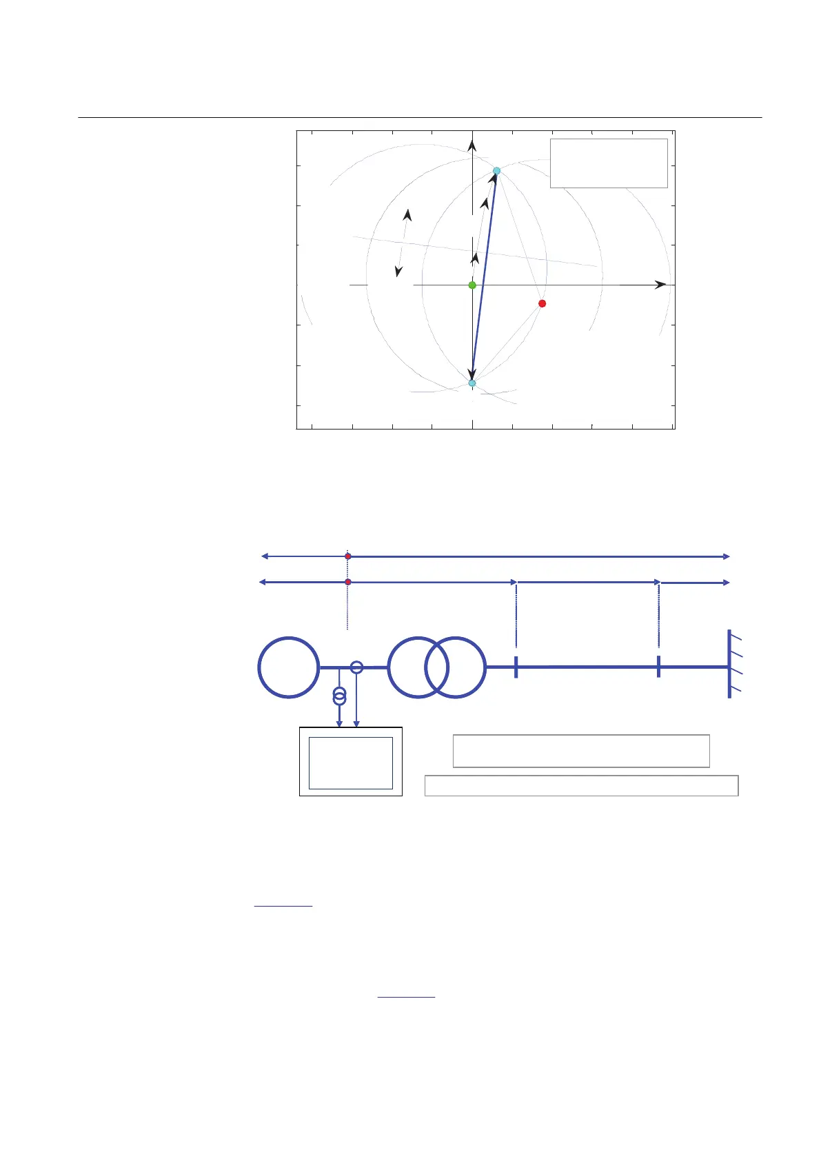
Z(R,X)
R
Zline
Zone 2
relay
←
Z-line
120°
←
Lens is the locus
of constant rotor (power)
angle, e.g. 120°.
Lens' width determined
by the setting StartAngle
X
Position of the OOS
relay is the origin of
the R - X plane
Zone 1
limit-of-reach
→
circle depends on
the position of the
points SE and RE
X-line
determined
by the
→
setting
ReachZ1
IEC10000112-1-en.vsd
IEC10000112 V1 EN
Figure 79: Construction of the lens characteristic for a power system
ll impedances must be referred to the generator voltage 13.8 k
ReverseZ(ReverseR, ReverseX)) ForwardZ(Forward
ll impedances must be referred to the generator voltage 13.8 k
IEC10000113 V2 EN
Figure 80: Example of an actual power system
To be able to automatically construct the lens characteristic for a system shown in
Figure 80, the actual power system must be modeled as a two-machine equivalent
system, or as a single machine – infinite bus equivalent system, the following
information is necessary: Zgen(Rgen, Xgen), Ztr(Rtr, Xtr), Zline(Rline, Xline),
Zeq(Req, Xeq), and the setting StartAngle, for example 120 degrees. All impedances
must be referred to the voltage level where the out-of-step protection relay is placed;
in the case shown in
Figure 80 the relay is connected to the terminals of the generator
and, therefore, the previous quantities shall be referred to the generator nominal
1MRK 502 048-UEN A Section 7
Impedance protection
167
Technical manual