IEC09000018-2-en.vsd
Chosen current
phasors
Chosen voltage
phasors
Complex
power
calculation
P
Derivation of
S(composant)
in Char angle
S(angle)
S(angle) <
Power1
t TRIP1
START1
Q
P = POWRE
Q = POWIM
S(angle) <
Power2
t TRIP2
START2
IEC09000018 V2 EN
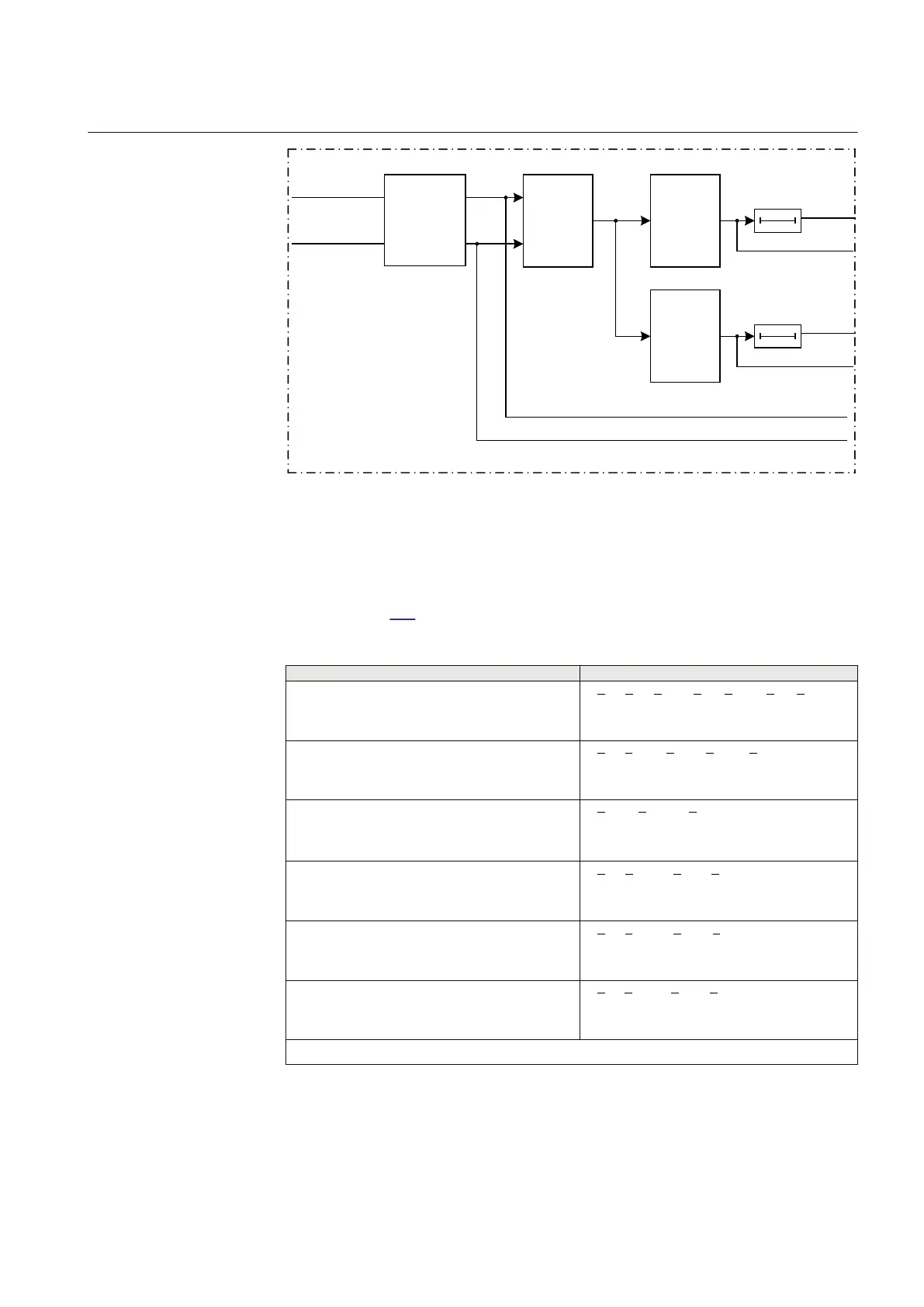
Figure 118: Simplified logic diagram of the power protection function
The function will use voltage and current phasors calculated in the pre-processing
blocks. The apparent complex power is calculated according to chosen formula as
shown in table 133.
Table 133: Complex power calculation
Set value:
Mode
Formula used for complex power calculation
L1, L2, L3
* * *
1 1 2 2 3 3L L L L L L
S U I U I U I= × + × + ×
EQUATION1697 V1 EN (Equation 64)
Arone
* *
1 2 1 2 3 3L L L L L L
S U I U I= × - ×
EQUATION1698 V1 EN (Equation 65)
PosSeq
*
3
PosSeq PosSeq
S U I= × ×
EQUATION1699 V1 EN (Equation 66)
L1L2
* *
1 2 1 2
( )
L L L L
S U I I= × -
EQUATION1700 V1 EN (Equation 67)
L2L3
* *
2 3 2 3
( )
L L L L
S U I I= × -
EQUATION1701 V1 EN (Equation 68)
L3L1
* *
3 1 3 1
( )
L L L L
S U I I= × -
EQUATION1702 V1 EN (Equation 69)
Table continues on next page
1MRK 502 048-UEN A Section 8
Current protection
237
Technical manual