IEC01000235_2_en.vsd
Activating
signal
LED
Reset
IEC01000235 V2 EN
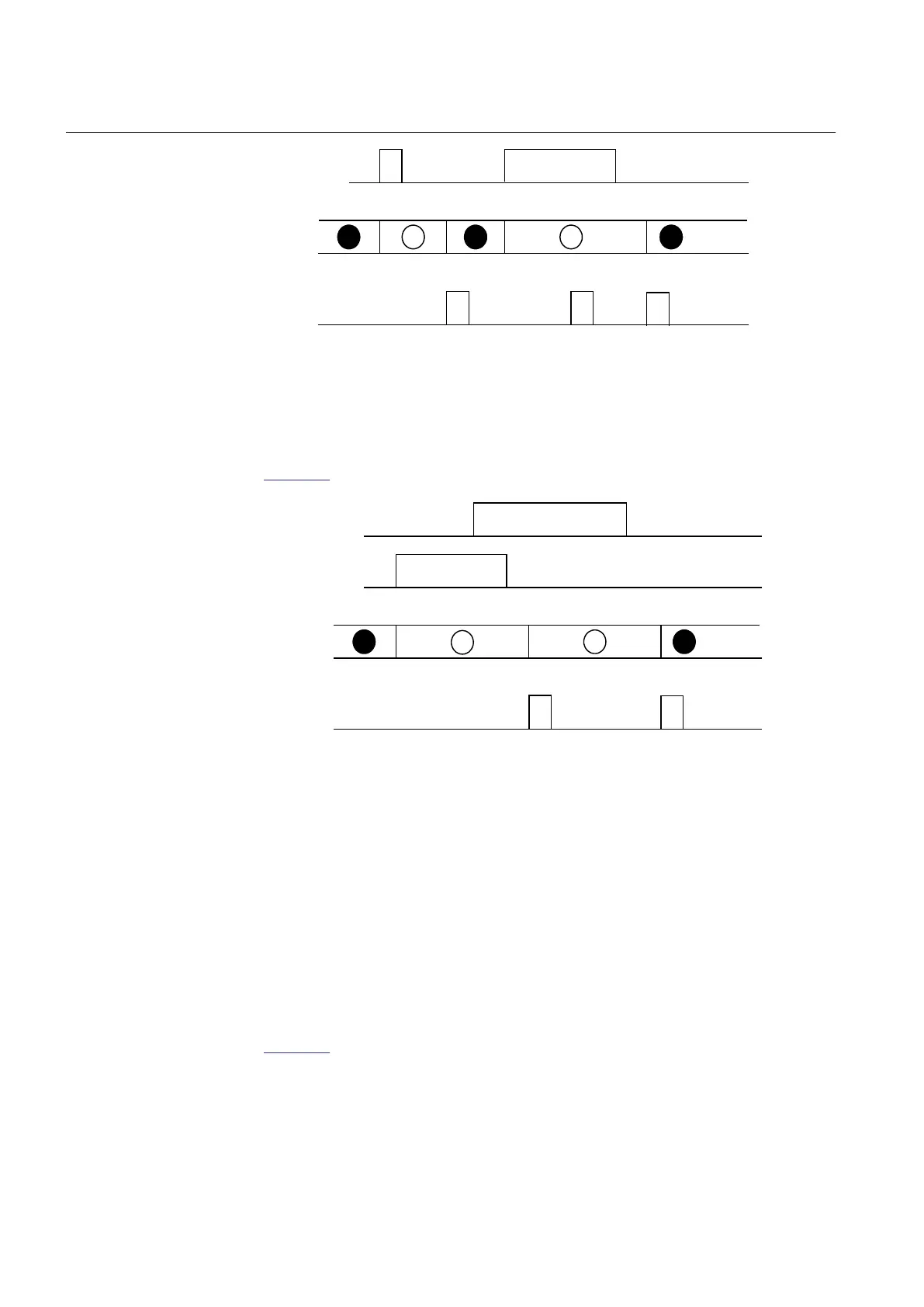
Figure 20: Operating Sequence 5 LatchedColl-S
That means if an indication with higher priority has reset while an indication with
lower priority still is active at the time of reset, the LED will change color according to
Figure 21.
Activating
signal RED
LED
Reset
IEC09000316_1_en.vsd
Activating
signal GREEN
R G
IEC09000316 V1 EN
Figure 21: Operating sequence 5, two colors
Sequence 6
LatchedReset-S
In this mode all activated LEDs, which are set to Sequence 6 (LatchedReset-S), are
automatically reset at a new disturbance when activating any input signal for other
LEDs set to Sequence 6 LatchedReset-S. Also in this case indications that are still
activated will not be affected by manual reset, that is, immediately after the positive
edge of that the manual reset has been executed a new reading and storing of active
signals is performed. LEDs set for sequence 6 are completely independent in its
operation of LEDs set for other sequences.
Timing diagram for sequence 6
Figure 22 shows the timing diagram for two indications within one disturbance.
Section 5 1MRK 502 048-UEN A
Local Human-Machine-Interface LHMI
74
Technical manual