32
RTCA SP Instrument Operator’s Manual
B
B
Installation
Resistor Plate Verifi cation of RTCA SP Instrument
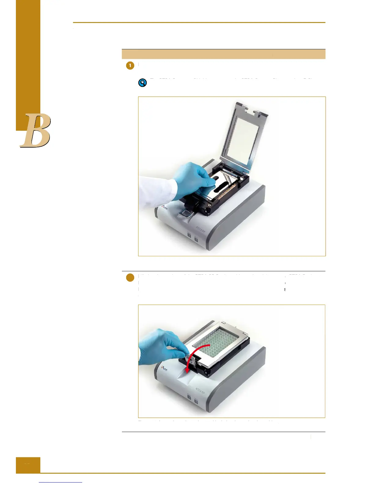
Place the RTCA Resistor Plate 96 in the RTCA SP Station
Lift the clamp plate of the RTCA SP Station. Insert the RTCA Protector Shield 96 into
the cradle pocket of the RTCA SP Station as shown in Figure 18.
The RTCA Protector Shield 96 protects the RTCA Contact Pins 96, when E-Plates
96 are inserted or removed from the RTCA SP Station.
Figure 18: Insert the RTCA Protector Shield 96 in the RTCA SP Station.
Lift the clamp plate of the RTCA SP Station with one hand, insert one RTCA Resistor
Plate 96 (with plate cover) in the cradle pocket of the RTCA SP Station (Figure 19).
Ensure that the angled corners are inserted fi rst and that the plate is fully inside the
cradle pocket.
Figure 19: Insert the resistor plate and lock the clamp plate in position.
RTCA SP Instrument Operator’s Manual
Resistor Plate Verifi cation of RTCA SP Instrument
Place the RTCA Resistor Plate 96 in the RTCA SP Station
Lift the clamp plate of the RTCA SP Station. Insert the RTCA Protector Shield 96 into
the cradle pocket of the RTCA SP Station as shown in Figure 18.
The RTCA Protector Shield 96 protects the RTCA Contact Pins 96, when E-Plates
96 are inserted or removed from the RTCA SP Station.
Figure 18: Insert the RTCA Protector Shield 96 in the RTCA SP Station.
Lift the clamp plate of the RTCA SP Station with one hand, insert one RTCA Resistor
Lift the clamp plate of the RTCA SP Station with one hand, insert one RTCA Resistor
Lift the clamp plate of the RTCA SP Station with one hand, insert one RTCA Resistor
Lift the clamp plate of the RTCA SP Station with one hand, insert one RTCA Resistor
Plate 96 (with plate cover) in the cradle pocket of the RTCA SP Station (Figure 19).
Plate 96 (with plate cover) in the cradle pocket of the RTCA SP Station (Figure 19).
Plate 96 (with plate cover) in the cradle pocket of the RTCA SP Station (Figure 19).
Plate 96 (with plate cover) in the cradle pocket of the RTCA SP Station (Figure 19).
Ensure that the angled corners are inserted fi rst and that the plate is fully inside the
Ensure that the angled corners are inserted fi rst and that the plate is fully inside the
Ensure that the angled corners are inserted fi rst and that the plate is fully inside the
Ensure that the angled corners are inserted fi rst and that the plate is fully inside the
Figure 19: Insert the resistor plate and lock the clamp plate in position.