49
Maintenance and Care
D
D
For example, if well G10 would have a contact problem, the RTCA Contact Pin for G10
and/or the corresponding Pin for ground (GND) would have to be exchanged. e
positions are marked by arrows in Figure 29.
If well G10 has a contact problem but wells E10, F10 and H10 do not, then replace the
RTCA Contact Pin for G10.
If well G10 has a contact problem and wells E10, F10 and H10 do also, then replace
the GND Pin for the group E10 to H10.
e following procedure is suggested for exchanging the RTCA Contact Pins 96:
Remove RTCA Protector Shield 96 from the cradle pocket of the RTCA SP Station.
Blow any dust away from the entire surface of the RTCA SP Station.
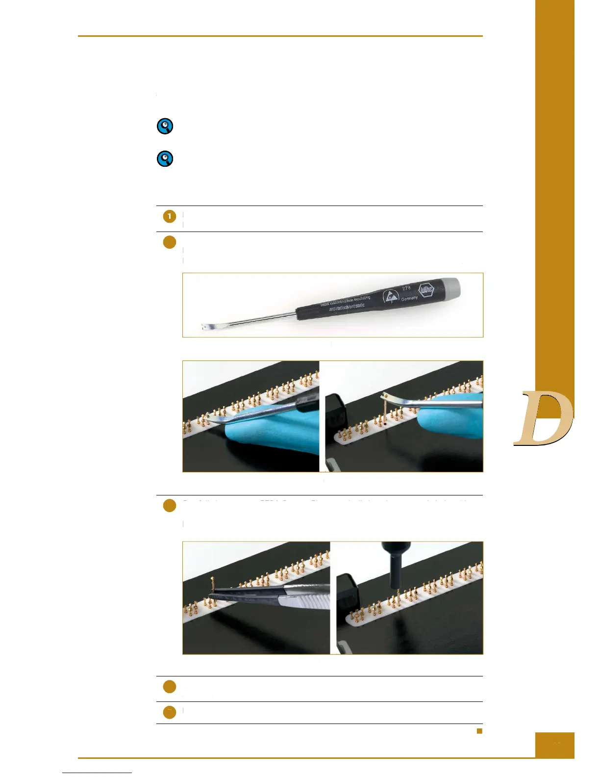
Carefully position the RTCA Contact Pin into the groove of the RTCA Contact Pin
Replacement Tool (Figure 30), hold gently at the neck position of the RTCA Contact
Pin, then vertically extract the defective RTCA Contact Pin as shown in Figure 31.
Figure 30: RTCA Contact Pin Replacement Tool
Figure 31: Extraction of an RTCA Contact Pin
Carefully insert a new RTCA Contact Pin 96 vertically into the receptacle hole, without
bending, then use the RTCA Contact Pin Insertion Tool to push down the RTCA Contact
Pin 96 vertically down close to the bottom surface. The RTCA Contact Pin 96 should
be at the same height as the other RTCA Contact Pins 96 (Figure 32).
Figure 32: Replacing RTCA Contact Pins 96
Use the dust blower to blow the surface around the RTCA Contact Pins 96 to remove
any dust.
Insert the RTCA Protector Shield 96.
Cleaning and Exchanging the RTCA Contact Pins 96