EasyManua.ls Logo

Acea RTCA SP Instrument - Page 48

Acea RTCA SP Instrument
60 pages
Print Icon
To Next Page IconTo Next Page
To Previous Page IconTo Previous Page
Loading...
48
RTCA SP Instrument Operators Manual
D
D
Exchange the RTCA Contact Pins 96
In case of a damaged or failed RTCA Contact Pin, the respective pin can be exchanged
with a new one using an easy and quick process.
Defective RTCA Contact Pins 96 should only be replaced according to the instructions
described in this manual.
Spare RTCA Contact Pins 96 are included with RTCA SP Instrument. If more RTCA
Contact Pins 96 are needed, please contact your local ACEA representative.
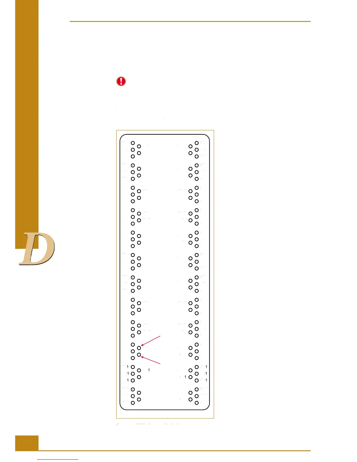
e wells concerned (e.g., G10) can be correlated with the RTCA Contact Pin that is likely
to be responsible for contact problems with the aid of Figure 29:
Front side
F1
H1
E1
G1
GND
D1
A1
C1
GND
B1
F2
H2
E2
G2
GND
D2
A2
C2
GND
B2
F3
H3
E3
G3
GND
D3
A3
C3
GND
B3
F4
H4
E4
G4
GND
D4
A4
C4
GND
B4
F5
H5
E5
G5
GND
D5
A5
C5
GND
B5
F6
H6
E6
G6
GND
D6
A6
C6
GND
B6
F7
H7
E7
G7
GND
D7
A7
C7
GND
B7
F8
H8
E8
G8
GND
D8
A8
C8
GND
B8
F9
H9
E9
G9
GND
D9
A9
C9
GND
B9
F10
H10
E10
G10
GND
D10
A10
C10
GND
B10
F11
H11
E11
G11
GND
D11
A11
C11
GND
B11
F12
H12
E12
G12
GND
D12
A12
C12
GND
B12
Figure 29: RTCA Contact Pin elds.
The front side of the RTCA SP Station is where the lock handle is located.
Cleaning and Exchanging the RTCA Contact Pins 96
48
D
D
D
D
D
D
D
D
D
RTCA SP Instrument Operators Manual
D
D
D
D
D
D
D
D
D
Exchange the RTCA Contact Pins 96
In case of a damaged or failed RTCA Contact Pin, the respective pin can be exchanged
with a new one using an easy and quick process.
Defective RTCA Contact Pins 96 should only be replaced according to the instructions
described in this manual.
Spare RTCA Contact Pins 96 are included with RTCA SP Instrument. If more RTCA
Contact Pins 96 are needed, please contact your local ACEA representative.
e wells concerned (
e.g.
, G10) can be correlated with the RTCA Contact Pin that is likely
to be responsible for contact problems with the aid of Figure 29:
Front side
F1
H1
E1
G1
GND
D1
A1
C1
GND
B1
F2
H2
E2
G2
GND
D2
A2
C2
GND
B2
F3
H3
E3
G3
GND
D3
A3
C3
GND
B3
F4
H4
E4
G4
GND
D4
A4
C4
GND
B4
F5
H5
E5
G5
GND
D5
A5
C5
GND
B5
F6
H6
E6
G6
GND
D6
A6
C6
GND
B6
F7
H7
E7
G7
GND
D7
A7
C7
GND
B7
F8
H8
E8
G8
GND
D8
A8
C8
GND
B8
F9
H9
E9
G9
GND
D9
A9
C9
GND
B9
F10
H10
E10
G10
GND
D10
A10
C10
GND
B10
F1
1
H1
1
E1
1
G1
1
GND
D1
1
A1
1
C1
1
GND
B1
1
F12
H12
E12
G12
GND
D12
A12
C12
GND
B12
Figure 29: RTCA Contact Pin fi elds.
The front side of the RTCA SP Station is where the lock handle is located.
Cleaning and Exchanging the RTCA Contact Pins 96

Table of Contents

Related product manuals