5-6 – Main Rotor Track & Balance 5 Revision 3, Oct 2012
5.1.3. – Tracking Influence Setup
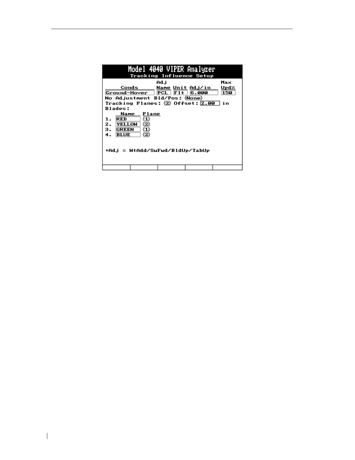
The tracking influence setup screen is used to define the type and number of adjustment units
used to move a blade 1.0 unit of measure at the condition listed.
Conditions: The condition name will be automatically entered and is not editable.
Adjustment Name: Using the keypad, enter a three-character identifier for the adjustment
type. Example = PCL (Pitch Change Link), SWP (Sweep), WGT (Weight), and TAB (Tab).
Unit: Using the keypad, enter a three-character identifier for the unit of adjustment type.
Example = FLT (Flat), PTS (Points), GMS (Grams), DEG (Degrees), and THO
(Thousandths).
Adjustments / in (mm): Enter the number of adjustment units to move the blade 1.0 unit of
measure. This will either be requested in Adj/in or Adj/mm depending on the measurement
units selected in the initial setup screen. In this example, it will take an adjustment of 6 flats
to move the blade tip one inch in ground or hover conditions.
Max ICF Update: This field is used to restrict the learning criteria for track adjustments. The
example uses 50%. With 50% selected, any movement over 50% of the expected result for a
given adjustment, and the analyzer will not update the ICF. Using the keypad, enter the
desired parameter to be placed in the setup.
No Adjustment Bld/Pos.: This field is used to designate a main rotor blade as a “no
adjustment blade.” This feature is used when the OEM suggests that no adjustments be
applied to a particular blade during a track and balance job. An optimized solution is
provided by the analyzer that requires no adjustments to the designated “No Adjustment
Blade”.
Tracking Planes: This field is used to designate the number of planes in which the main rotor
blades fly. If all blades fly in the same plane, select <1>. If there are two distinct planes for
the blade path select <2>.



 To Next Page