Viper 4040 User Manual
Revision 3, Oct 2012 6 Tail Rotor Balance – 6-3
Additionally, the tail rotor balance function assumes the adjustment will always be weight in
grams. If the chart uses an adjustment type such as the number of washers per IPS, simply
enter this number and overlook the label of grams.
WtPos, Add @: The lower portion of the screen provides fields for entry of the “WtPos”
names and “Add @” (move line) clock angles. Since this is a “Regular” chart setup, you will
only have to enter the move lines for the first two weight positions; the analyzer will
determine the rest.
• Starting with any of the weight positions, enter a name, up to six characters, in the first
field as shown.
• Next, press the [⇓] key to move one field to the right; enter the angle (in hours) of the
move line for this position. If the move line contains an angle in minutes, press the [⇓]
key again to move to the next field and enter the minutes.
Repeat the name and move line process for the second weight position, then enter the rest of
the weight position names and this chart is completed.
NOTE
Weight position names must be entered sequentially in either clockwise or counter clockwise
order. It does not matter what direction is chosen.
6.1.2. – Irregular Chart Forms
6.1.2.1. – Irregular Tail Rotor Chart
Setup
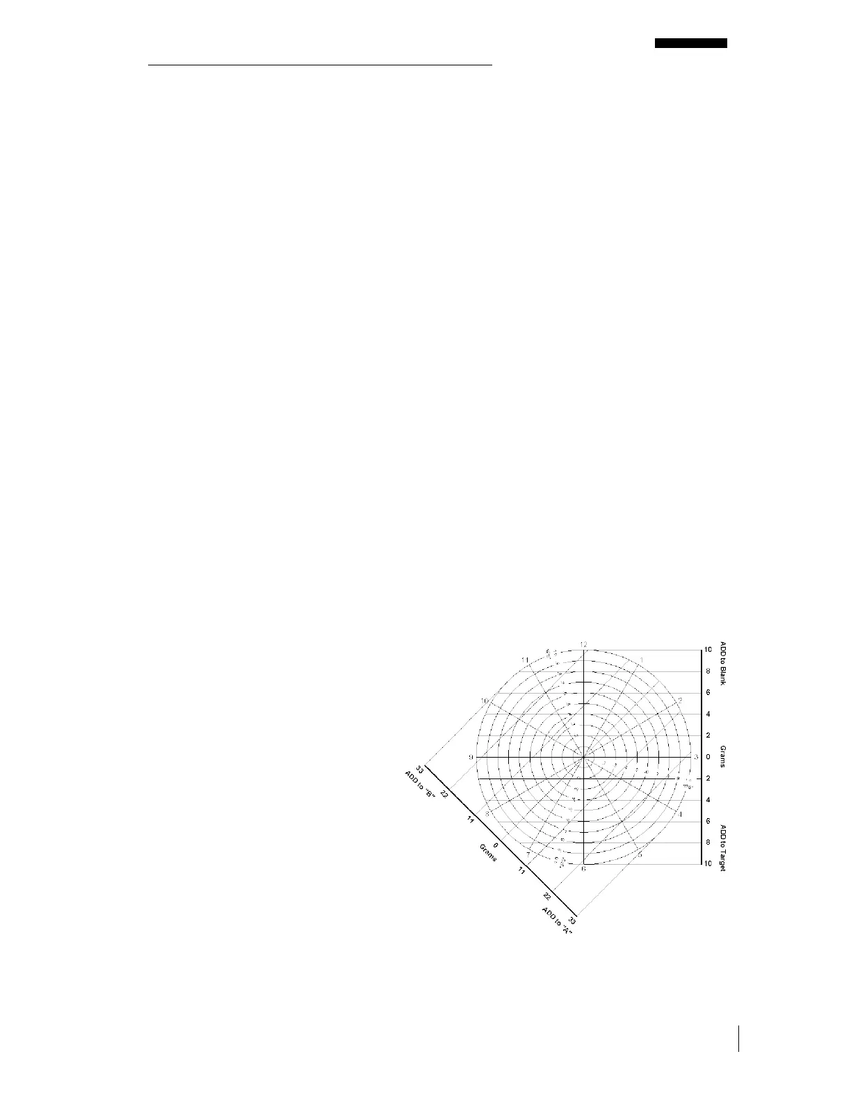
The tail rotor balance chart shown to
the right represents four adjustment
points, all of which utilize the addition
of weight as a correction type.
However, the ICF is different for two
of the points. Target and Blank have
an ICF of 10 grams per 1.0 IPS where
“A” and “B” have an ICF of 33 grams
per 1.0 IPS. The clock angle move
lines are not equally spaced around
the chart therefore it must use the
“Irregular” chart form in the analyzer.
Using this chart, follow the examples
below to properly define an
“Irregular” tail rotor chart setup in the
analyzer.



 To Next Page