5-14 – Main Rotor Track & Balance 5 Revision 3, Oct 2012
lateral chart(s), then any track adjustment influences required. When all charts have been
completed, press [ENTER] to save the setup and return to the “Main Rotor Manage Setups”
menu. Follow paragraphs 5.2.1.6 through 5.2.1.6.7 for a complete example of a typical main
rotor setup.
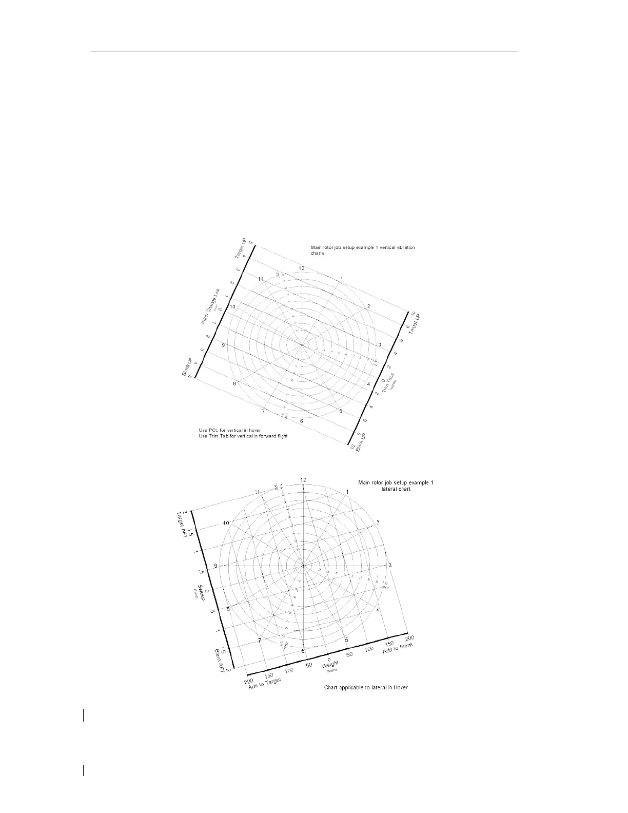
5.2.1.6. – Main Rotor Setup Example
This setup example is applicable to a helicopter type that utilizes pitch change link
adjustments to correct for vertical vibration in a hover, weight and blade sweep adjustments
for lateral vibration in a hover, and blade trim tab adjustments for vertical vibrations in
forward flight regimes. The polar charts used for this example are illustrated below.
Rotor diameter: 37.0 Feet. Lead/lag units are read in inches.
Rotor speed: 385 RPM/



 To Next Page