Viper 4040 User Manual
Revision 3, Oct 2012 5 Main Rotor Track & Balance – 5-15
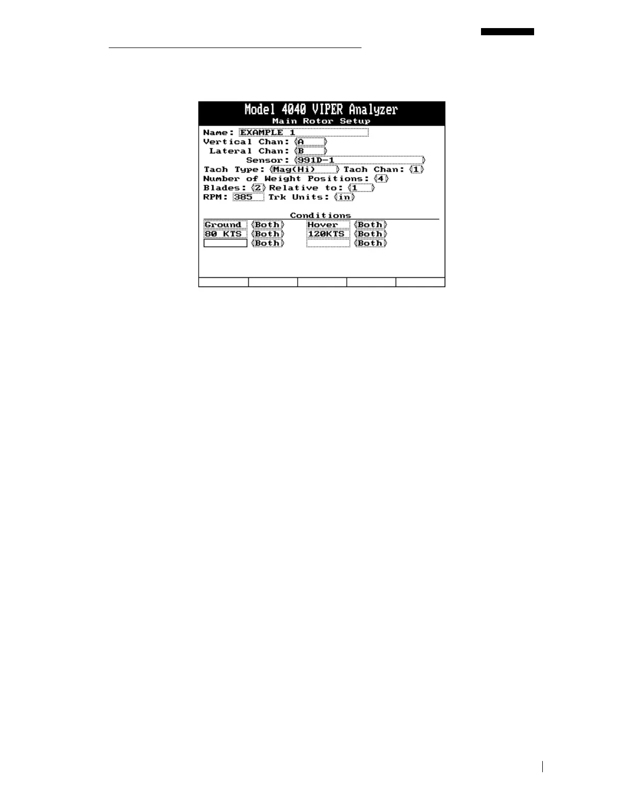
5.2.1.6.1. – Main Rotor Setup Screen
1. The name of the setup has been labeled as “EXAMPLE 1”.
2. Vertical vibration will be measured on channel “A”.
3. Lateral vibration will be measured on channel “B”.
4. The type of vibration sensor chosen for this setup is the “991D-1”.
5. The type of tachometer source for this setup is the “Mag(Hi)”.
6. The tachometer channel for this setup is channel “1”.
7. Looking at the lateral balance chart presented in paragraph 5.2.1.6, four weight positions
have been identified, Target – Blank sweep and Target – Blank weight.
8. The main rotor is a two bladed system.
9. Tracking will be displayed relative to blade number “1”.
10. Rotor speed is 385 RPM.
11. Track measurements will be displayed in “inches”.
12. Four conditions have been entered for this job, “GROUND”, “HOVER”, “FLT80”, and
“FLT120”. Both track and vibration will be measured and recorded for this setup.
Press [ENTER] to proceed to the next screen.



 To Next Page