5-16 – Main Rotor Track & Balance 5 Revision 3, Oct 2012
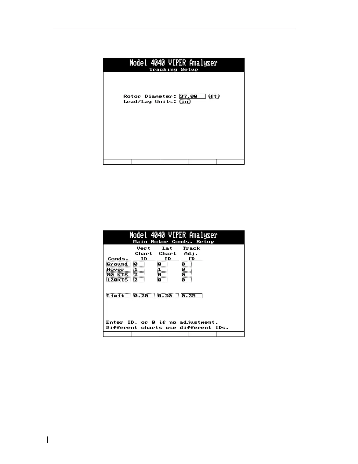
5.2.1.6.2. – Tracking Setup Screen
1. Enter “37.00” in the first block using the keypad.
2. Select “ft” for units of rotor diameter.
3. Select “in” for the display units of lead/lag data.
5.2.1.6.3. – Main Rotor Conditions Setup
Use the sample polar charts in section 5.2.1.6. In the “Main Rotor Conditions Setup” screen
above, two vertical charts and one lateral chart have been identified. The first vertical chart,
ID number “1”, will be used for a vertical measurement in hover only, while the second
vertical chart, ID number “2”, is for the average vertical measurement of both “FLT 80” and
“FLT120”. One lateral chart has been identified for the lateral measurement in “Hover” only.
The vibration limit for both the vertical and lateral measurements has been set at 0.20 IPS.
This main rotor setup will not use the tracking information measured by the analyzer for any
corrections; it will be for user reference only.



 To Next Page