Viper 4040 User Manual
Revision 3, Oct 2012 5 Main Rotor Track & Balance – 5-19
5. Max ICF Update is “50”%.
6. Rotation is “45” degrees.
7. The type of adjustment applied in accordance with this chart is trim tab in degrees;
therefore “DEG” has been entered.
8. The influence co-efficient for trim tab adjustment is “10.0” degrees per 1.0 IPS
vibration.
9. The Bld/Pos names entered from the chart are “TARGET” and “BLANK”.
10. The “MoveLine” for moving the “TARGET” blade up is “12:45”.
11. The “MoveLine” for moving the “BLANK” blade up is “6:45”.
When completed, press [ENTER] to continued.
5.2.1.6.7. – Lateral Hover Chart
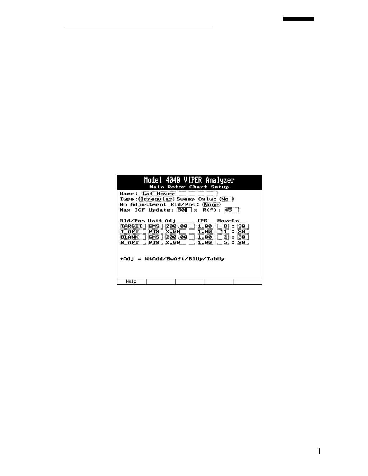
The last chart defined will be “Lateral: HOVER”. Use the lateral vibration chart in paragraph
5.2.1.6, to complete the steps below and properly define this chart.
1. The name has been automatically entered as “Lat: HOVER” from the “Main Rotor
Conditions Setup” screen and is non-editable.
2. The type of chart is “Irregular”.
3. Although this chart does utilize a sweep adjustment for balancing, it is not the only type
of adjustment used and therefore requires this entry to be left set as “No”.
4. No Adjustment Blade/Pos. is left as “None”.
5. Max ICF Update is “50”%.
6. Rotation is “45” degrees.
7. The first Bld/Pos name entered is “TARGET”, utilizing an adjustment unit of “GMS”
weight. The influence co-efficient for this point is “200.00” grams adjustment per “1.0”
IPS vibration. The Move line for this position is “8:30”.



 To Next Page