Viper 4040 User Manual
Revision 3, Oct 2012 5 Main Rotor Track & Balance – 5-7
Offset: This field will only appear after “Tracking Planes” above is set to 2 and the field is
exited. This field is used to define the optimum distance between multiple blade planes. The
analyzer will use this distance to properly position the groups of blades.
Blades: The blade names will default to those defined previously in the setup. If a change is
required, change the blade name to reflect the blades in passing order staring with the blade
that is over the nose when the tach and interrupter are aligned. This will be the name used in
the track display and when viewing available adjustments.
Plane: This field will only appear after “Tracking Planes” above is set to 2 and the field is
exited. This field is used to identify how the blades will be grouped. Blades flying in the
same plane require identical “Plane” entries.
Press [ENTER] to save the setup.
5.2. – Setup Process
This section covers the complete setup process in the 4040 Viper for the main rotor balance
functions.
5.2.1. – Main Rotor Setup
The following paragraphs illustrate each of the screens necessary to define and store an
enhanced main rotor setup.
5.2.1.1. – Main Rotor Setup Screen
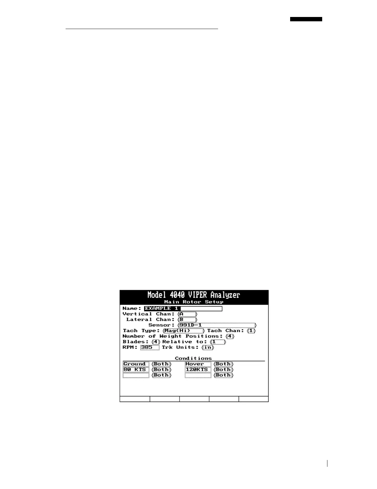
The first screen to complete is the “Main Rotor Setup” banner screen. As shown in the
example below, some fields in this screen have default values that appear automatically. You
can use this information if appropriate or input your own specific setup information using the


 To Next Page