6-4 - Tail Rotor Balance 6 Revision 3, Oct 2012
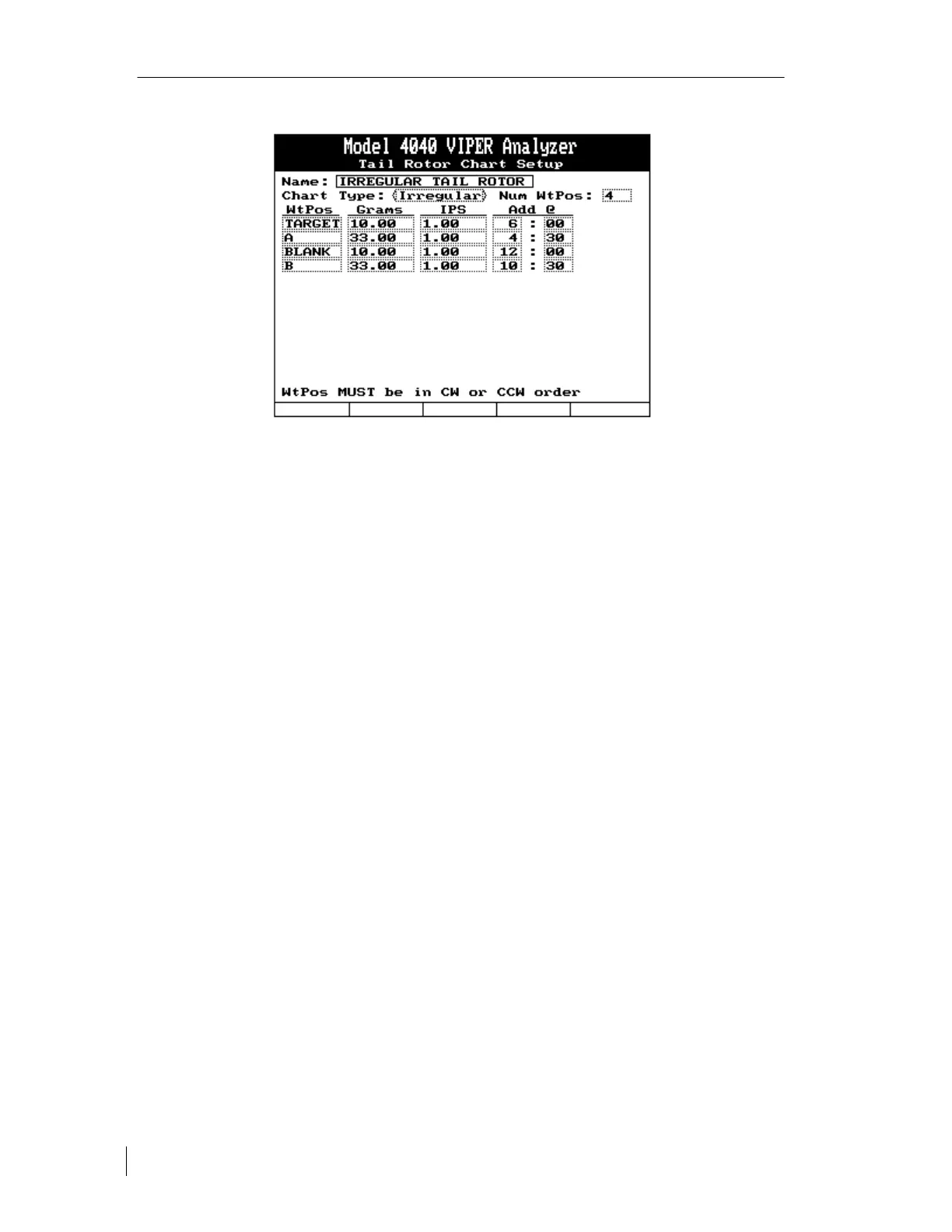
Name: The name of the chart will be automatically inserted from the main setup screen for a
tail rotor job.
Chart Type: Select “Irregular” as the chart type.
No. of WtPos: Enter the number of weight positions used as indicated by the polar chart, in
this case 4. You can input from 2 to 13 positions as needed. After pressing the [⇓] key to exit
the field, the value entered in this field will change the remainder of the screen to allow input
of each weight position’s ICF.
Wt/Pos, Grams, IPS, Add @:
• Starting with any of the correction points on the chart. Enter the weight position name in
the first field up to six characters. “TARGET” is the first weight position name in our
example.
• Press the [⇓] key and move to the next field. Enter the amount of adjustment portion of
the ICF under “Grams”. This example uses “10.00” grams.
• Press the [⇓] key and enter the amplitude reference for the amount of adjustment just
entered. For this example, enter “1.0” IPS
Press the [⇓] key to move to the “Add @” field. Enter the clock angle move line for this
point. For the “TARGET” weight position the move line is “6:00”.
Perform this for each adjustment point shown on the chart and the setup is complete.
Note:
Weight position names must be entered sequentially in either clockwise or counter clockwise
order. It does not matter what direction is chosen.


 To Next Page