2.4. Connections
Connections of your eBox must be accomplished in the order described below, before you connect the
power supply adapter cable to the eBox POWER socket.
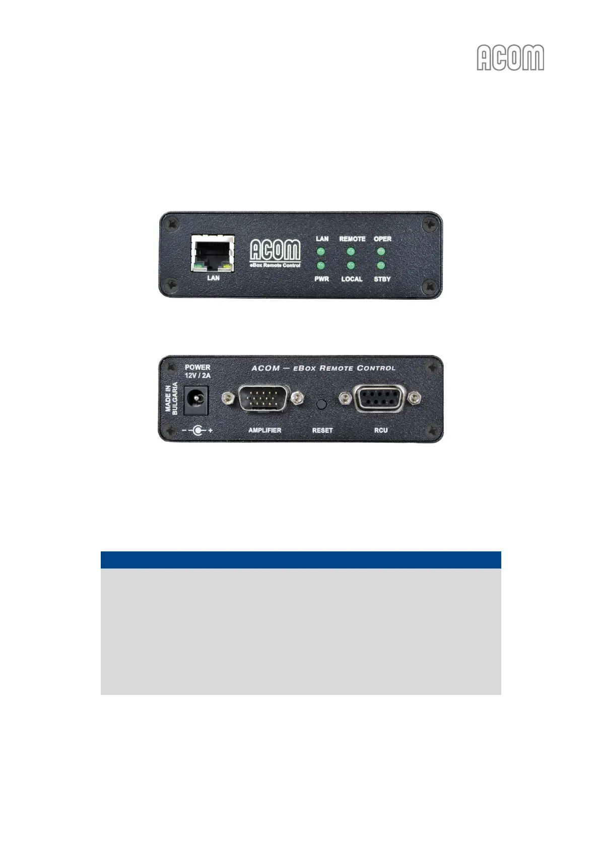
Figure 2-4 Front panel - Connection and indicators
Figure 2-4 Front panel - Connection and indicators
Figure 2-5 Rear panel - Connections
Figure 2-5 Rear panel - Connections
a) eBox to amplifier connection
Please, see Figure 2-5 Rear panel - Connections.
NOTICE
Be careful to use the correct connection cable between AMPLIFIER connector (on eBox
rear panel) and:
- ACOM 600S, 700S or 1200S amplifier RS-232 connector (on amplifier rear panel), or
- ACOM 2000A amplifier REMOTE CONTROL connector (on amplifier rear panel).
The connection cable must correspond to your amplifier model and should be specified
when you order the eBox.
Using an inappropriate cable may cause a serious damage to the eBox device and your
amplifier!