5.2.1. ACOM 2000A Amplifier Settings
a) Amplifier panel
Please, see Figure 5-5 eBox with ACOM 2000A connected, Pos. (a).
Changes to this panel can be made only while the amplifier is switched OFF.
Panel functional buttons:
• OFF and ON
Switch the amplifier OFF or ON;
• Save
When it is pressed the amplifier model change in a panel is saved;
Panel functional fields:
• Model
Allows selection of connected amplifier model. The supported models are ACOM 2000A,
600S, 700S, and 1200S;
• State
Displays the current state of the amplifier: Starting, Warm-up, Initializing, Standby, Powered
OFF, Powered OFF (Local Mode), or Operate;
• Front/Rear tube
Displays the tubes serial numbers;
• Serial
Displays amplifier serial number;
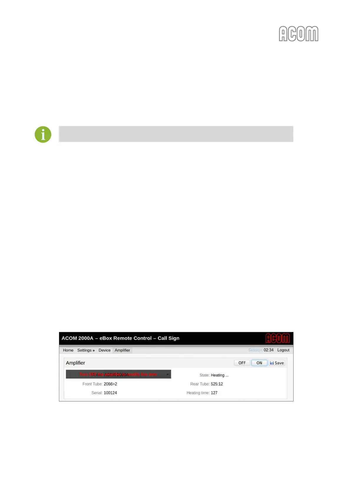
• Warm-up time
You can see this counter only during the Warm-up process (see Figure 5-4 eBox Warm-up time
counter). This is a counter for the seconds until the warm-up end.
Figure 5-4 eBox Warm-up time counter
Figure 5-4 eBox Warm-up time counter