User's Manual | ACOM eBox | Ethernet Remote Control Device
S e c t i o n INSTALLATION | Page
19
of
60
b) Ethernet LAN connection
Please, see Table 2-4 eBox LAN socket wiring.
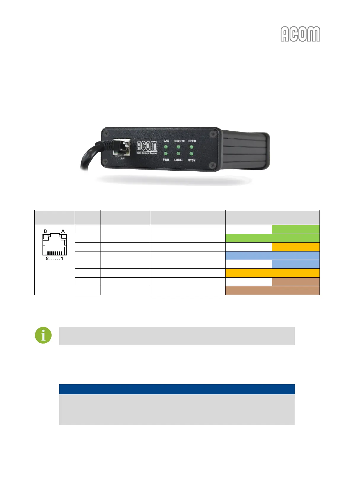
Connect a standard Ethernet plug-terminated cable between eBox LAN socket (located on front panel,
RJ-45 type, see Figure 2-8 below) and your Ethernet hub/switch.
Figure 2-8 Front panel with Ethernet cable connected
Figure 2-8 Front panel with Ethernet cable connected
Table 2-4 eBox LAN socket wiring
Colors (T568A pin assignment)
RJ-45 socket,
8-pin, female
(Rear panel
view)
Table 2-4 eBox LAN socket wiring
You can order standard Ethernet cable with suitable length from your local IT store.
c) Power supply connection
NOTICE
In order to avoid any damage (not covered by the warranty), check carefully to be
certain that the voltage and power input plug of the eBox corresponds to your mains.
Always connect the power adapter last and disconnect it before all other connectors.
Connect the power supply adapter cable to the eBox POWER socket (on eBox rear panel, see Figure 2-5
Rear panel - Connections).