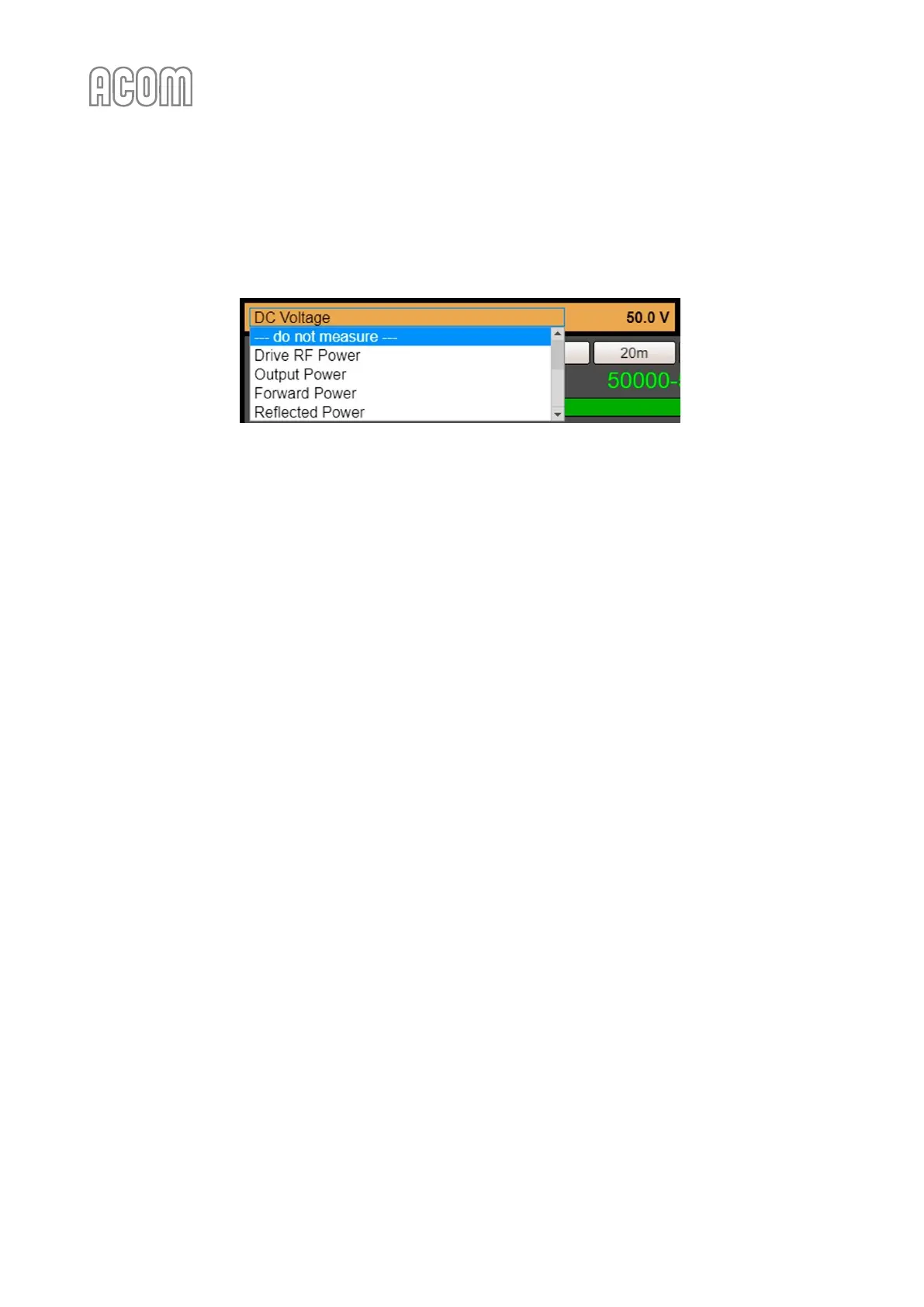
By default, --- do not measure --- is being displayed. To select a parameter, click over the panel (parameter
name) and choose the desired one from the scrollable list (see Figure 6-6 eBox with ACOM 600S, 700S, or
1200S - Parameter 1 selection).
Figure 6-6 eBox with ACOM 600S, 700S, or 1200S - Parameter 1 selection
Figure 6-6 eBox with ACOM 600S, 700S, or 1200S - Parameter 1 selection
g) Parameter 2 of 2
Please, see Figure 6-5 Operating of eBox with ACOM 700S, Pos. (g).
It is used analogously to Parameter 1.
h) Band
Please, see Figure 6-5 Operating of eBox with ACOM 700S, Pos. (h).
A set of ten buttons for direct selection of a frequency band 160 m - 10 m.
i) Segment
Please, see Figure 6-5 Operating of eBox with ACOM 700S, Pos. (i).
Choose a frequency segment. Digital and graphical segment reading within the selected band. Used only
when a Remote Automatic Antenna Tuner and Switch ACOM 04AT is installed.
j) Drive RF
Please, see Figure 6-5 Operating of eBox with ACOM 700S, Pos. (j).
This bargraph displays the input (driving) power.
k) LED indicators
Please, see Figure 6-5 Operating of eBox with ACOM 700S, Pos. (l).
These four LED-like indicators might warn you about the following:
• Overheat indicator: Amplifier is overheated and is disabled until it cools down;
• CAT indicator: There is an active CAT interface;
• TX Disable indicator: Transmission is disabled due to critical fault;
• Transmit indicator: Ongoing transmission (ON AIR); The indicator illuminates whenever
KEY-IN amplifier input is keyed, i.e., the transceiver goes into transmit mode. Flashing
indicates that the transmission request cannot be executed for some technical reason.
l) Mode
Please, see Figure 6-5 Operating of eBox with ACOM 700S, Pos. (l).
Amplifier mode of operation, selection buttons:
• OPERATE mode;
• STANDBY mode.