• μUSB connector, for configuration using the Thyro-Tool Pro software
• 9-pin digital I/O connector, with 6 digital inputs
• 9-pin analog I/O connector, with 3 analog inputs, and 3 analog outputs
• Optional 16-pin analog/digital I/O connector, with 4 digital inputs, 3 digital
outputs and 3 analog inputs
• Optional 16-pin digital I/O connector, with 9 digital inputs and 3 digital outputs
Up to two of the optional 16-pin I/O ports may be installed in the unit. Each I/O port
line can be reconfigured to serve any function, as needed for the application.
☞ Important
This manual describes the default configuration. Though these functions are
fully configurable, AE recommends not changing the default configuration.
☞ Important
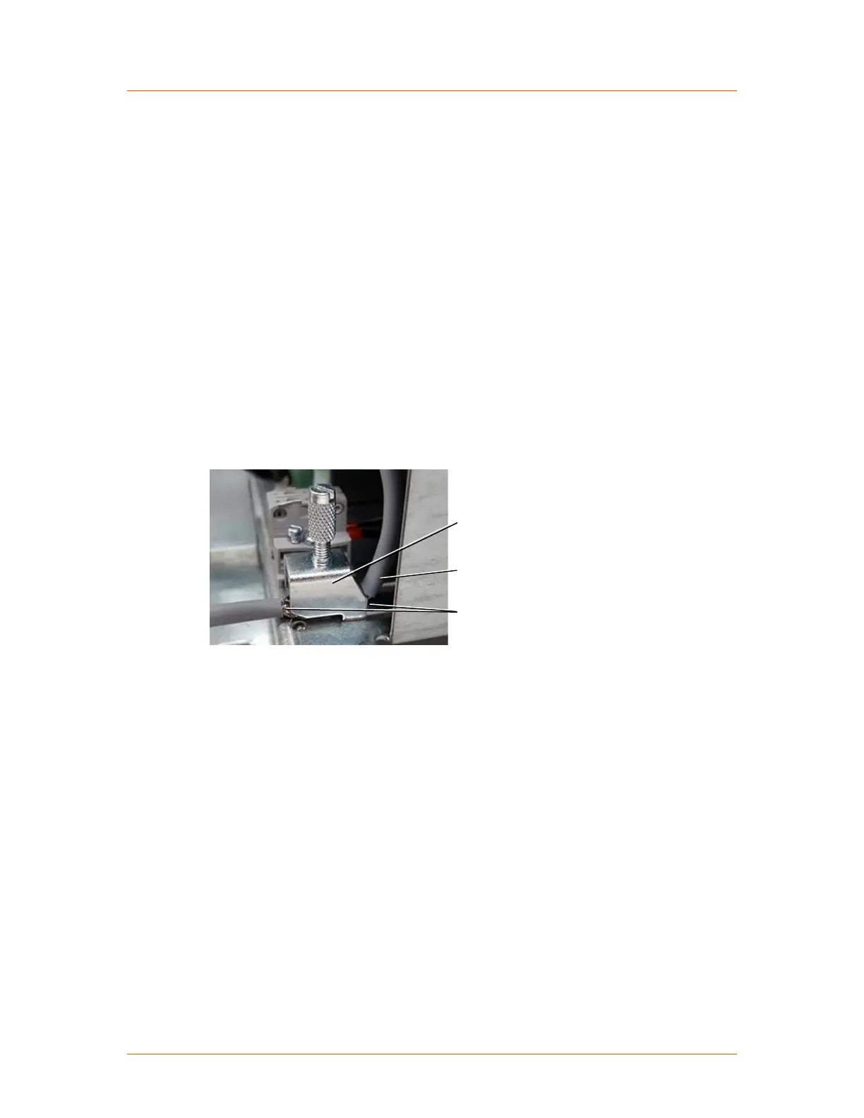
All digital and analog control cables must be shielded. Connect the cable
shields to the shield clamp on the unit as shown in the following figure.
Shield clamp
Cable
Exposed shield
Figure 4‑3. Shield clamp
Advanced Energy
®
Thyro-PX
®
Power Controller
57010148-00G Communication Controls 4‑5
 Loading...