Primary VSC is particularly suitable for large load currents (I
Load
> I
Controller
) with
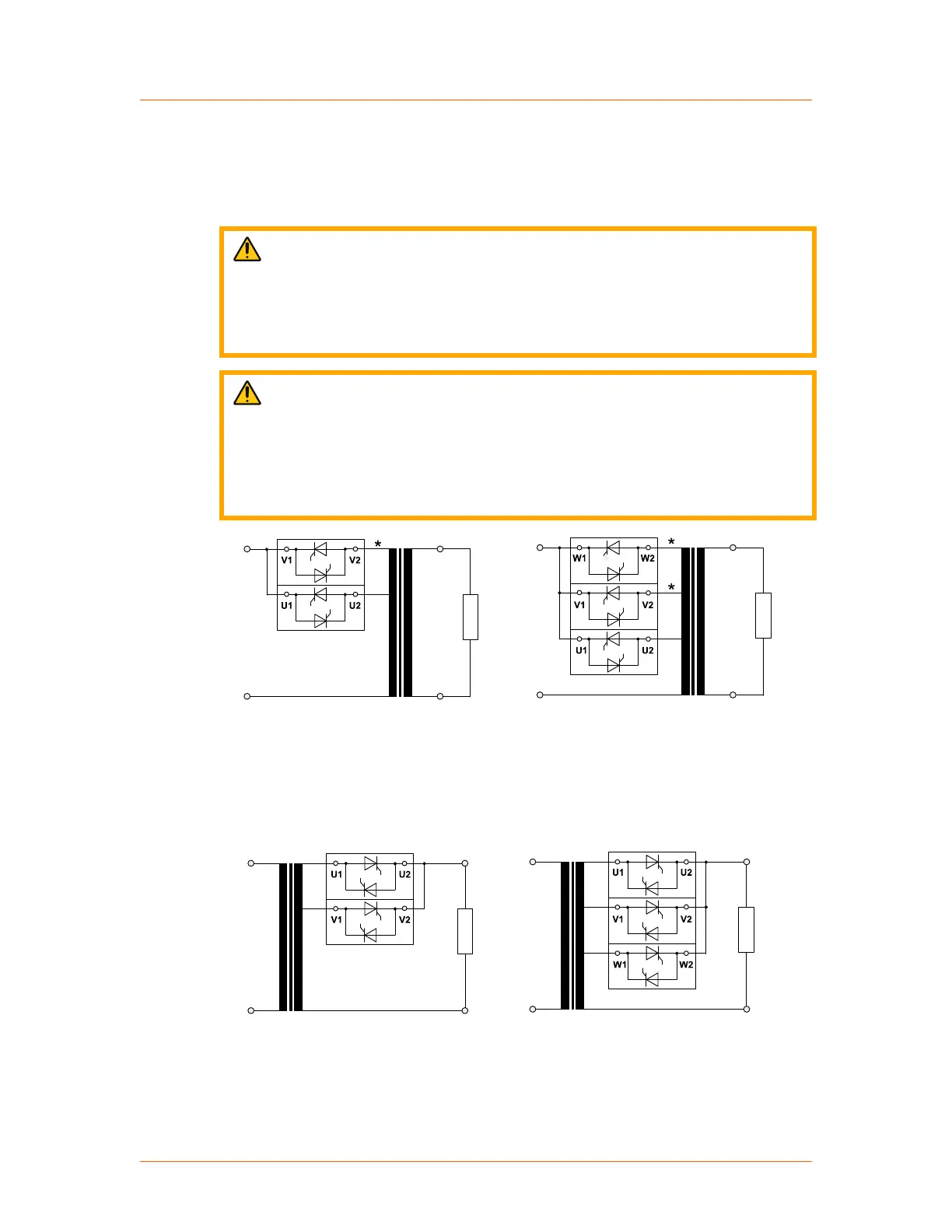
smaller voltages. One transformer is used for each load. The following illustrations
show the two stage and three stage VSC connections. Details can be found in the
Thyro-PX VSC connection diagrams, Figure 5‑30 and Figure 5‑31.
CAUTION:
In the primary VSC configuration, the mains voltage is stepped up on the
inactive power controller outputs, marked * in the following figure. The
transformer must be designed so that this voltage does not exceed the type
voltage (500 V or 690 V) of the unit, or the unit will be damaged.
ATTENTION:
Dans la configuration principale de VSC, la tension de l'alimentation secteur
est élevée sur les sorties du contrôleur de puissance inactive, indiqué par *
dans l'illustration suivante. Le transformateur doit être conçu de façon à ce
que la tension n'excède par la tension type de l'appareil (500 V ou 690 V);
autrement l'appareil pourrait être endommagé.
Mains MainsTransformer Transformer
Load
Load
Primary VSC 2 Primary VSC 3
Figure 5‑27. Primary VSC
Secondary VSC is particularly suitable if many heaters are being supplied from one
transformer. Through the improvement of the power factor, a larger transformer can
dispense more active power and supply additional loads (if required).
Mains
Mains
Transformer Load
Secondary VSC 3
Secondary VSC 2
Load
Transformer
Figure 5‑28. Secondary VSC
Advanced Energy
®
Thyro-PX
®
Power Controller
57010148-00G Installation, Setup, and Operation 5‑24
 Loading...