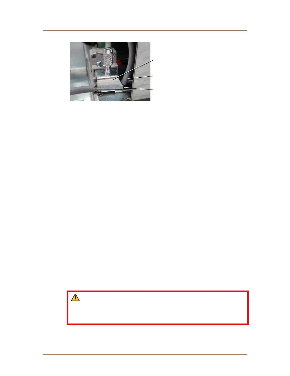
Shield clamp
Cable
Exposed shield
Figure 5‑32. Shield clamp
The following signals are always required for operation of the device: SETPOINT,
PULSE LOCK.
☞ Important
By default, the unit is configured to require a customer supplied PULSE LOCK
jumper. The unit may be customer configured to not require this jumper.
Complete the following steps to connect each control cable required for your
installation. A plug-in, screw-terminal block is provided for each control connector.
1.
Verify that the control cable conductors are sized between 0.14 mm
2
and
1.5 mm
2
(30 AWG and 14 AWG).
2. Prepare the end of the control cable:
a. Strip 50 mm (2″) of the cable jacket.
b. Expose the cable shield for connection to the shield clamp.
c. Strip 7 mm (0.28″) of insulation from each conductor.
3. Connect each conductor to the plug-in, screw-terminal block.
4. Plug the block into the power controller.
5. Connect the cable shield to the shield clamp.
Related Links
• “Analog and Digital I/O” on page 4‑4
Connecting Load and Auxiliary Power
DANGER:
RISK OF DEATH OR BODILY INJURY. Disconnect and lockout/tagout all
sources of input power before working on this unit or anything connected to
it.
Advanced Energy
®
Thyro-PX
®
Power Controller
57010148-00G Installation, Setup, and Operation 5‑30
 Loading...