EasyManua.ls Logo

Advanced MxPro4

Advanced MxPro4
72 pages
To Next Page IconTo Next Page
To Previous Page IconTo Previous Page
Loading...
16
2.3.4 Remounting the Chassis
Carefully replace the chassis and locate onto the upper two screws. Replace the bottom two screws and tighten
all four screws to hold the chassis securely to the back box.
Reconnect the chassis earth cable to the spade terminal in the rear of the enclosure.
2.3.5 Recommended Cable Routing Arrangement
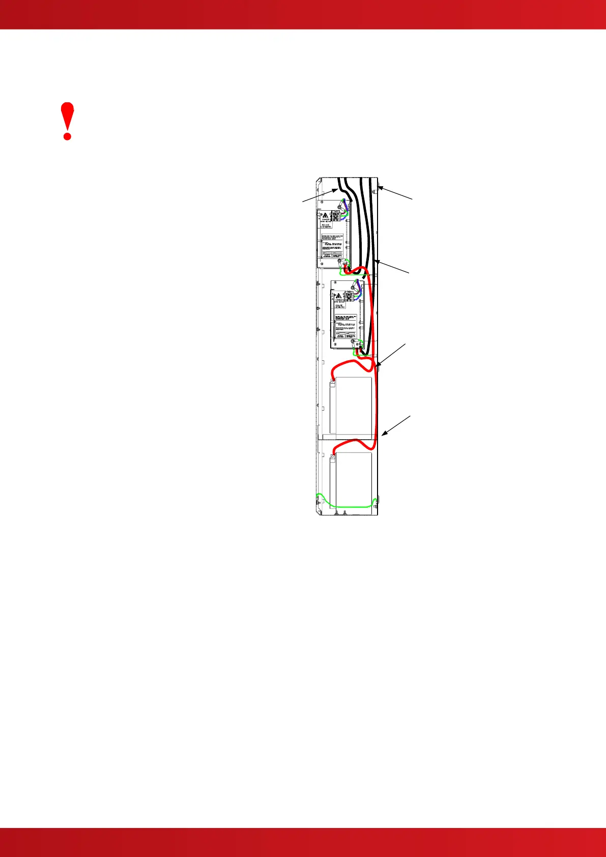
It is recommended that the routing
arrangement shown in the diagram
opposite be employed.
Segregate the low voltage wiring
(Loop Circuit, Sounder Circuits,
RS485 and AUX Supply) from the
AC Mains Wiring.
Segregate any wiring connected to
the relay contacts.
Eyelets are provided in the rear of
the back box to enable the cables to
be securely fastened using tie-
wraps.
Sounders and AUX wiring should be
routed behind the chassis assembly
and tie-wrapped to the back box.
Cable screens / shields should be
connected to the back box using Bus
Bars provided near the knockout
holes.
Refer to Appendix 2
Recommended Fire Rated Cables
for further information on cable types
to be used.
Refer to specific sections on how to
install AC Mains input and loop,
sounder, relay and AUX outputs
circuits.
Use front
knockout rows for
upper chassis
cables
Use rear knockout
rows for lower
chassis cables
Route battery
cables through
hole in upper
battery shelf
Ensure that the
hole is protected
by a grommet.
Field
Installation
Wiring
Battery Wiring
Internal arrangement showing recommended routing of
cables.
www.acornfiresecurity.com

Table of Contents

Other manuals for Advanced MxPro4

Related product manuals