3.2 Recommended Programming Procedure
Step 1 – SET-UP, Define General Set-up Information (Phone Numbers, etc.).
Step 2 – PASSWORDS, Define Level 2 and Level 3 Passwords as required.
Step 3 – AUTO-LEARN, Let the panel learn the devices on the loop(s).
Step 4 – VIEW DEVICES, Enter Zone Numbers, Location text and Change Group Assignments if required.
Step 5 – OUTPUTS, Program Output Groups as required.
Step 6 – ZONES, Enter Zone Texts as required.
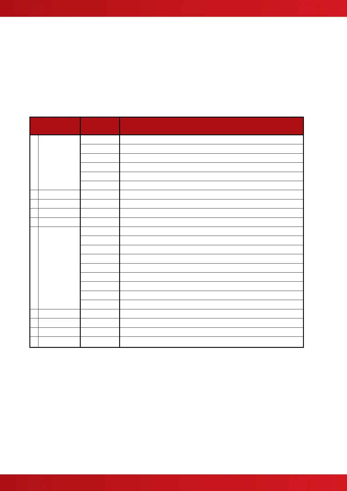
3.3 Level 3 Menu Functions
The following table gives a list of the Level 3 Menu Functions, the sub-functions available within each main
function and a brief description for each function.
View, test and configure the loop devices
Learn the Devices Present on the Loop.
Calibrates devices on the loop
View line input and output voltages, load current and loop driver software version
View the line quality assessed by each device
Auto address (sequentially) the devices
Cancel Level 3 Access and return to Level 2 Menu Options.
Configure the Operating Characteristics of the Output Circuits.
Change the Date and Time Settings.
View Zones and Inputs that are reporting a fire alarm condition.
View Zones and Inputs that are reporting a fault condition.
View Zones and Inputs that are reporting an alarm condition during test.
View Zones, Inputs and Outputs that are disabled.
View the current state of Zones and Inputs.
View the current operational condition of all output circuits.
View the operational state, voltage & current loading of the panel I/O.
Configure the Level 2 and Level 3 passwords.
Change the default zone assignments and output groups for all panel I/O.
Enable the PC Link for transfer of configuration data to and from the panel.
Configure General Operating Parameters.
www.acornfiresecurity.com
www.acornfiresecurity.com