3.3.2.7.6 Special Sensitivity Mode SSM/Clock
In addition to the “SENSITIVITY ADJUST MODE”, a device can also run in a “SPECIAL SENSITIVITY MODE”
(SSM) under time-clock control.
The Mx4200V supports 10 independent, 7-day time clocks.
The Mx4400V supports 10 independent, 7-day time clocks.
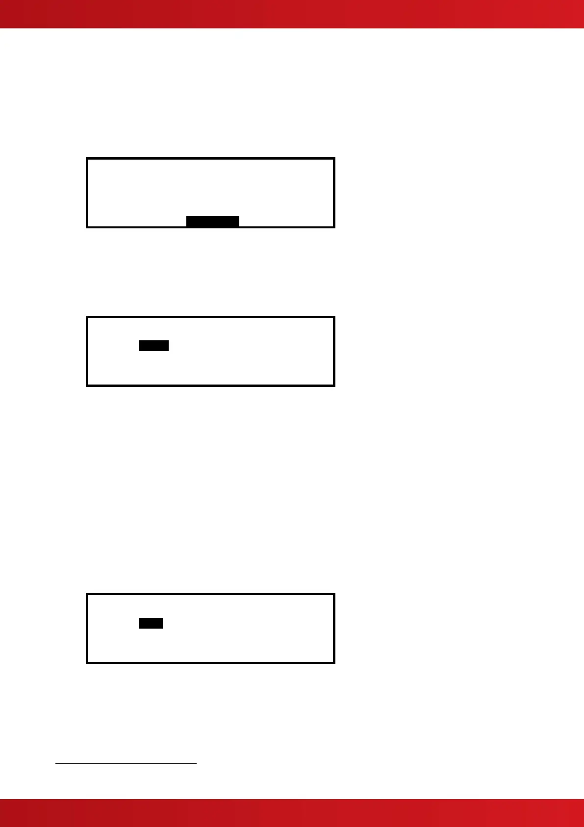
With the SAM/SSM Option highlighted, press the ✔ button to view the Special Sensitivity Mode settings. For
example:
SPECIAL SENSITIVITY MODE (SMOKE )
[SSM/Clock = 2 ][ Alarm = 192 ]
[ Mode = 1 ][ Pre-Alarm= 160 ]
[ Delay = 0s][ Min.Value= 0 ]
[SAM/SSM]
In the above example the panel is using special sensitivity mode 2 (and time clock number 2). Enter “0” in the
SSM/Clock field to cancel Special Sensitivity Mode.
A number must be entered in the SSM/Clock field to select the appropriate SSM number and time clock. To
view the time clock settings, highlight the SSM/Clock field, and press the ✔ button.
For example:
[Time Clock 2]
DAY ON -> OFF ON -> OFF
MON 00:00 00:00 19:00 00:00
TUE 00:00 06:30 00:00 00:00
WED 00:00 00:00 00:00 00:00
THU 00:00 00:00 00:00 00:00
The panel supports two independent times for each day of the week during which the SSM mode will be
switched on (i.e. during which the Special Sensitivity Mode settings are active)
In the above example the SSM will be active between 19:00 on Monday and 06:30 on Tuesday.
Press the buttons to select the appropriate time field and use the number buttons to enter the required
times. Press the ‘Esc’ button to return to the previous menu display.
Every type of device (the device type is shown in the top, right hand corner) supports unique SSM settings for
each SSM/Clock number. In the previous example the Special Sensitivity Mode settings have been defined for a
Multi-Sensor that is using SSM/Clock number 2. If other Multi-sensors on the same panel also require the same
settings, then you only need to set them to SSM/Clock 2. If instead another Multi-Sensor requires a different
setting, use a different SSM/Clock number.
3.3.2.8 O/P Group
The Output Group assigned to the Sounder or Relay Devices determines the manner in which the outputs will
operate when a fire alarm or other programmed condition occurs.
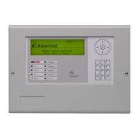
For example:
[Loop 1 Devices] <More>
Address O/P Group
020.0 199
021.0 199
022.0 199
023.0 199
Use the number buttons to change the value of the O/P Group setting.
By default, all Loop Output devices are assigned to Output Group 199.
For detailed information and guidance on the programming and use of Output Groups, refer to Section 5.4
Note: Synchronisation of sounders can only be performed for Output Groups 1 – 8.
See Appendices for device specific information.
www.acornfiresecurity.com
www.acornfiresecurity.com