5.5.3.8 Zone Monitor Module
The VMCZ100 is a 2-wire
conventional detector interface
compatible with the AURORA range of
conventional detectors (S100, S200,
S300 and S400).
The module employs an end-of-line
capacitor to supervise the circuit for
open circuit conditions.
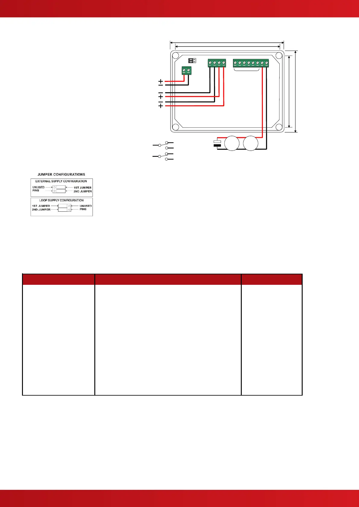
The IP54 enclosure dimensions, fixing
points and terminal wiring is shown
opposite. 20mm knockouts are
provided in the enclosure.
The unit may be powered by the loop
or by a separate 24VDC EN54-4 PSE.
Set both jumpers in accordance with
the following arrangement (label on
the unit).
CONVENTIONAL DETECTOR CIRCUIT
The detector circuit current limit, alarm current and reset time
can be adjusted using the PC CONFIG Tool to a range of
values to suit the particular application.
The default settings are:
Current Limit: 10mA
Alarm Current: 7.5mA
Reset Time: 1 second
A dual pole relay output is also provided that is
configurable and can be used to control (recent
reset activation) the power to the detection devices.
Contacts Rating: 30V AC/DC, 2A Resistive
The following zone circuit operating characteristics can be configured using the PC Tool.
Note: To save loop power, the VMCZ100 will disconnect the power from the zone circuit once an alarm has
been latched.
Calculate the standby current of the connected devices and select the current limit and alarm limit values to suit
the installation. Ensure that the standby current is not more then 50% of the alarm current.
The default settings are recommended for most installations. If the installation includes call points or switches
with series resistors, the current limit may require setting to 15mA or 20mA depending on the resistor value to
prevent the recognition of a short circuit condition rather than an alarm condition – see table above. For
example: If the call point employs a 270 Ω series resistor select a current limit of at least 15mA.
www.acornfiresecurity.com
www.acornfiresecurity.com