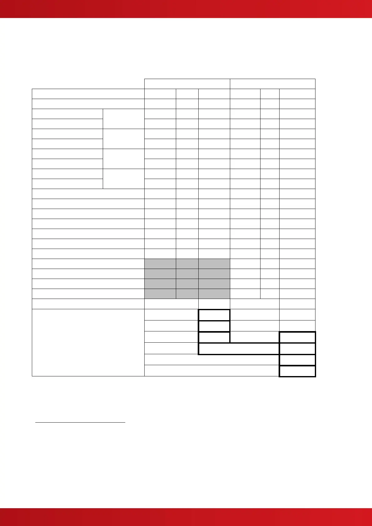
5.3 Appendix 3 – Battery Standby Calculation Chart
Use the following charts and associated notes to calculate the size of the batteries required to ensure operation
of the installation in the event of AC Mains power failure.
5.3.1 Mx-4200V / Mx-4400V / Mx-4800V
Mxp-003 AdNeT Network Card
Mxp-009 AdNeT PLUS Network Card
Mxp-025 LED Indicator – 20 Zone
Mxp-013-050 / 100 LED Indicator
Auxiliary Supply Output
20
Total Load (Quiescent + Alarm) =
x 1.25
21
(Battery De-rating factor) =
This chart is applicable to each chassis in the Mx-4800V panel.
Use the detector manufacturers’ technical information to calculate the load on the loop for both the quiescent condition and fire alarm
condition for all loop devices. By default, a maximum of 5 detector / call point LED indicators will be turned on in a fire alarm condition. (This
number can be changed via the PC Programming Tool).
The calculated loop loading must be multiplied by a factor of 1.25 to calculate the actual current draw from the batteries. This is to take
into account voltage conversion and conversion efficiency in generating the supply for the loop.
Not available on Mx-4200V.
Refer to separate data sheets for the additional modules can be powered from the panel AUX Output to determine the AUX loading
currents. For example, the modules can include 8-Way Output, 8-way Input, Modem, Sounder Splitter, Shop Interface, etc. The sum of all
these additional currents should be entered in these fields.
The alarm load should be doubled to allow for changes in battery efficiency for loads in excess of the recommended C/20 discharge rate.
The total load calculated should be multiplied by a de-rating factor of 1.25 to allow for changes in battery efficiency over time. The above
calculation is in accordance with the recommendations in BS5839-1: 2002.
www.acornfiresecurity.com
www.acornfiresecurity.com