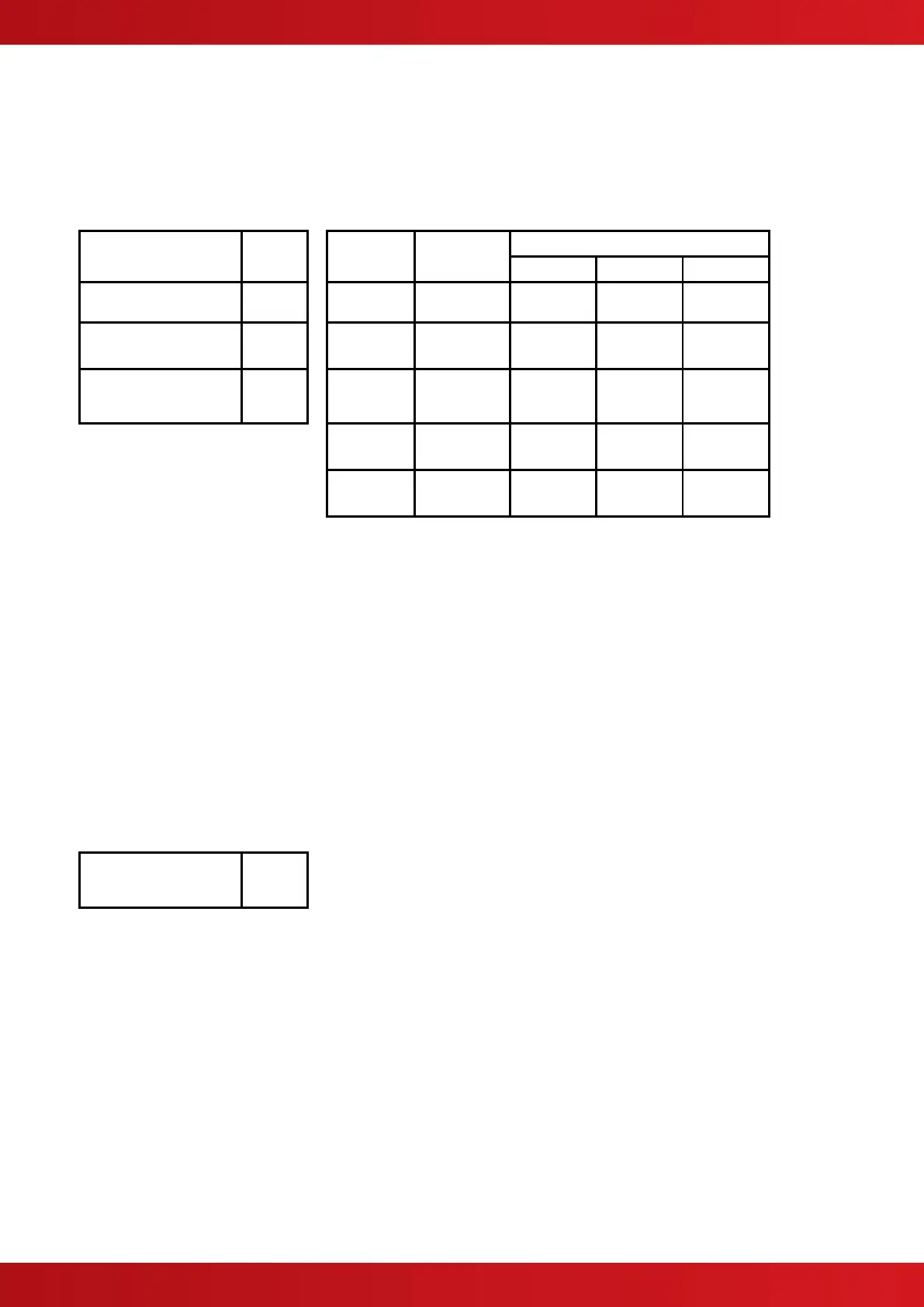
5.2.1 Detector Loop Lengths
With the above cables, loops can be up to 2Km in length. However, care must be taken when designing the
system to take into account the maximum loop loading. The voltage drop (load current x cable resistance) over
the cable always needs to be taken into account to ensure the devices receive an adequate supply voltage. The
following table gives recommendations for a loop. (It may be possible to extend the lengths where the devices
are distributed evenly – refer to the VEGA device data sheets and loop calculator for further information on
calculating loop loading, cable cross sectional area and loop distance).
Maximum Circuit
Impedance
Maximum Capacitance
(Core-Core)
Maximum Capacitance
(Core-Screen)
Insulation Resistance
(Core-Core and Core-
Screen)
NB: Maximum Circuit Impedance is the sum
of the resistance of both cable conductors.
5.2.2 Sounder Circuit Lengths
The voltage drop on each alarm circuit should be calculated to ensure that the minimum voltage at the end of
the circuit exceeds the minimum required by each sounding device at the minimum alarm circuit output voltage.
The voltage at the end of the circuit is given by:
Minimum Alarm Voltage = V
OUT(MIN)
– (I
ALARM
x R
CABLE
)
Minimum Output Voltage (V
OUT(MIN)
) is V
BAT(MIN)
– 0.5V = 20.5V
Alarm Current (I
ALARM
) is the sum of the loads presented by the sounding devices in alarm
Cable Resistance (R
CABLE
) is the sum of the cable resistance in both cores x cable length.
Cable Resistance (R
CABLE
) for 1.0mm
2
is 0.036Ω / metre
Cable Resistance (R
CABLE
) for 1.5mm
2
is 0.024Ω / metre
Cable Resistance (R
CABLE
) for 2.5mm
2
is 0.015Ω / metre
Insulation Resistance
(Core-Core and Core-
Screen)
www.acornfiresecurity.com
www.acornfiresecurity.com