FWA-3260 User Manual v02_20160302.docx Copyright 2014 Advantech Co. Ltd. All rights reserved. Page 10
List of Tables
Table 1: Packaging List ..................................................................................................................... 15
Table 2: PXE BIOS Options ................................................................................................................ 22
Table 3: System components ........................................................................................................... 27
Table 4: Available Product Versions ................................................................................................. 27
Table 5: Specifications...................................................................................................................... 29
Table 6: Applicable Safety Regulations ............................................................................................. 30
Table 7: Applicable EMC Regulations ............................................................................................... 31
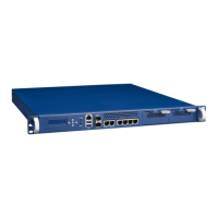
Table 8: Front elements ................................................................................................................... 32
Table 9: Rear elements .................................................................................................................... 32
Table 10: Xeon D SKUs for Network and Enterprise Storage Infrastructure ...................................... 34
Table 11: DIMM mapping ................................................................................................................. 35
Table 12: Validated DIMMs .............................................................................................................. 35
Table 13: USB Ports .......................................................................................................................... 35
Table 14: SATA Ports ........................................................................................................................ 36
Table 15: Validated SATA drives ....................................................................................................... 37
Table 16: COM Ports ........................................................................................................................ 37
Table 17: SMBus Devices .................................................................................................................. 38
Table 18: PCIe devices ...................................................................................................................... 42
Figure 19: Display of CPU temperature ............................................................................................ 44
Table 20: Thermal Sensors ............................................................................................................... 45
Table 21: Product Labels .................................................................................................................. 47
Table 22: FRU Data Synced to the DMI Tables .................................................................................. 47
Table 23: Bypass States and LED behaviour...................................................................................... 50
Table 24: Accessories ....................................................................................................................... 50
Table 25: BIOS Setup: Main Menu .................................................................................................... 53
Table 26: Platform Setup: COM1 Console Redirection Menu Items .................................................. 56
Table 27: USB Configuration Menu .................................................................................................. 58
Table 28: Trusted Computing Menu ................................................................................................. 58
Table 29: Trusted Computing Menu with TPM2.0 ............................................................................ 60
Table 30: Virtualization Menu .......................................................................................................... 61
Table 31: Platform Management Menu ........................................................................................... 63
Table 32: Processor Configuration Menu ......................................................................................... 65
Table 33: Northbridge Configuration Menu ..................................................................................... 67
Table 34: Hardware Setup: PCI Subsystem Menu Items ................................................................... 68
Table 35: Hardware Setup: QPI configuration Menu Items .............................................................. 69
Table 36: Hardware Setup: South Bridge configuration Menu Items ................................................ 71
Table 37: Hardware Setup: SATA configuration Menu Items ............................................................ 71
Table 38: Hardware Setup: USB configuration Menu Items .............................................................. 72
Table 39: Hardware Setup: ACPI configuration Menu Items ............................................................. 73
Table 40: Hardware Setup: Runtime Error logging Menu Items ........................................................ 74
Table 41: Server Mgmt configuration Menu Items ........................................................................... 75
Table 42 Boot Configuration ............................................................................................................ 77
Table 43: CSM Configuration Menu .................................................................................................. 78
Table 44: Save & Exit Menu Options ................................................................................................ 80
Table 45: Console connector pin assignment ................................................................................... 94
Table 46: Stacked USB Type A connector pin assignment ................................................................. 95
Table 47: RJ45 10/100/1000 Base-T connector pin assignment ........................................................ 96
Table 48: RJ45 connector LED indication .......................................................................................... 96
Table 49: BIOS POST Codes ............................................................................................................ 102
Table 50: Single AC Power Supply Specification ............................................................................. 103