2 Overview
IST Series UPS (10kVA-200kVA)
User Manual
14
NO. Name Illustration
○
,2
AC/DC indicator
On (green): rectifier works normally.
On (red): rectifier abnormal.
○
,3
DC/AC indicator
On (green): inverter works normally.
On (red): inverter abnormal.
○
,4
BYP. indicator
On (green): bypass output.
On (red): bypass abnormal.
○
,5
BATT. LOW indicator On (red): battery is low-voltage.
○
,6
OVERLOAD indicator On (red): output is overload.
○
,7
“ON” combination button
Press the two buttons for 3s, the system will power
on.
○
,8
“OFF” combination button
Press the two buttons for 3s, the system will power
off.
○
,9
button
Press the button, the system will power outage
immediately.
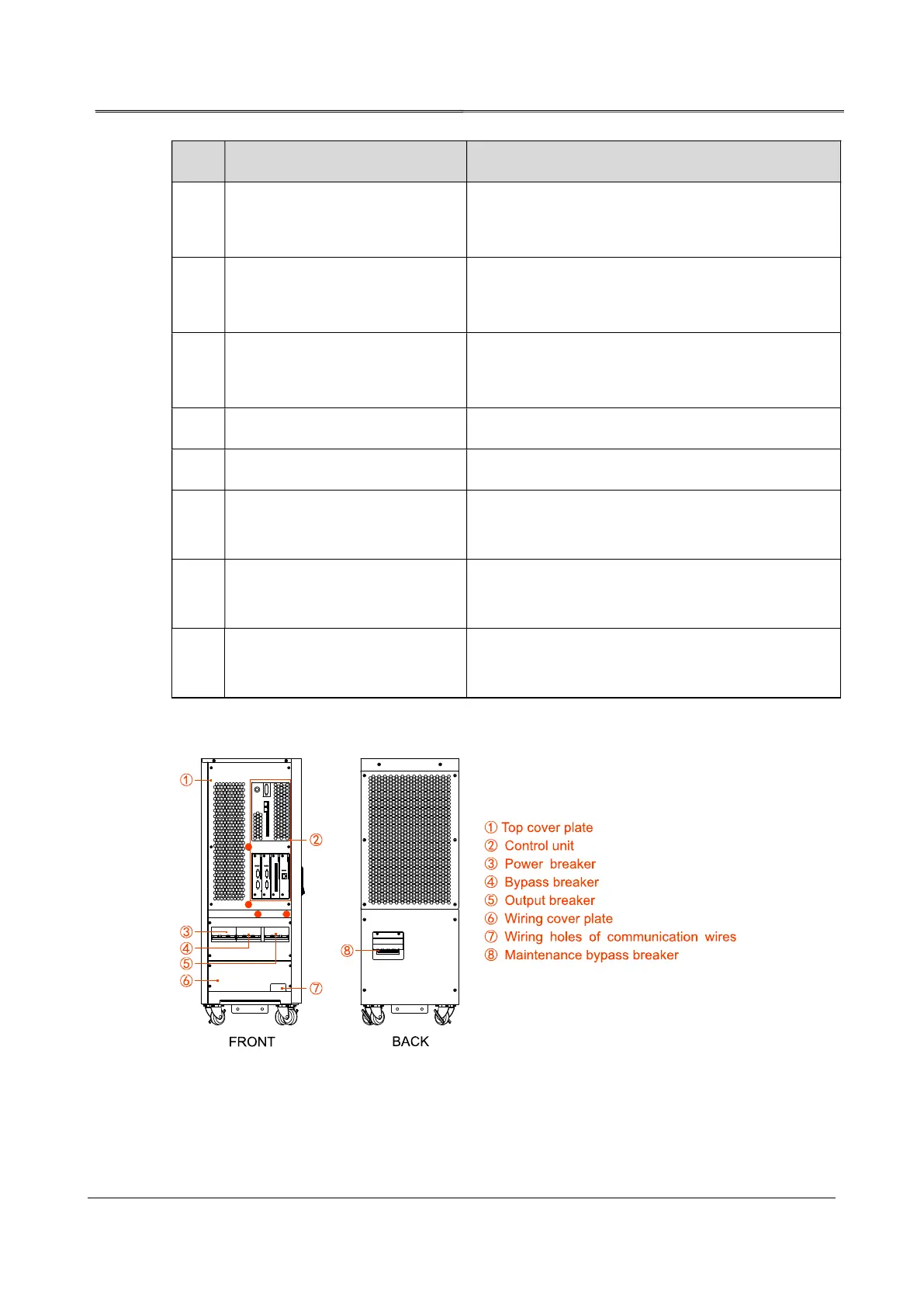
2.3.2 Structure Layout (Open Door)
Figure2-7 Structure layout diagram of 10kVA, 20kVA, 30kVA, 40kVA