Micro-Ohmmeter Model 6250
29
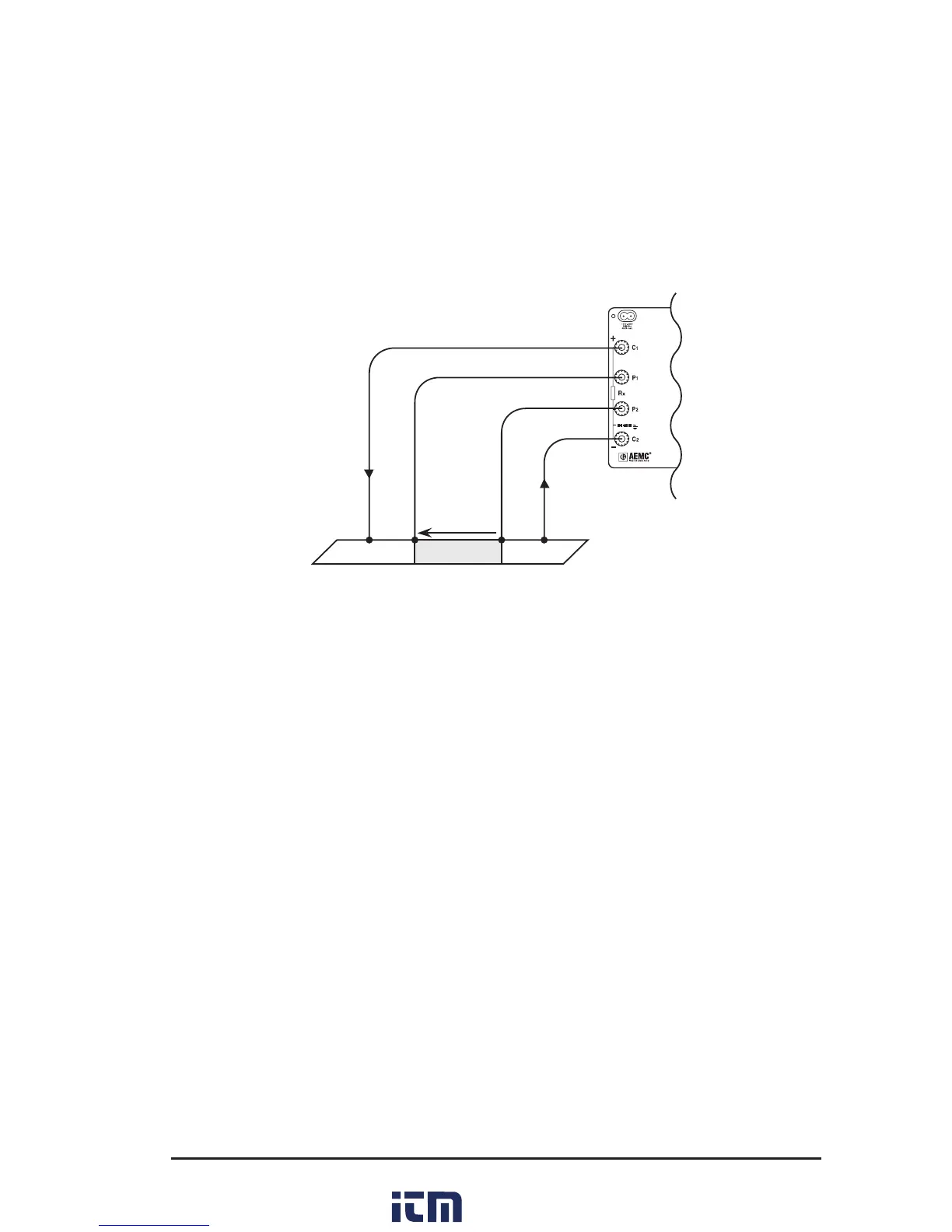
4.3.2 Test Lead Connection
The measurement leads are connected using the four binding posts on the
left side of the front panel as shown in Figure 4-3.
Connect the two red leads to terminals C1 and P1. Connect the two black
leads to terminals C2 and P2.
Any drop in the voltage on the load terminals is measured between the two
“voltage” (V) leads, P1 and P2. The current leads (C1 and C2) can deliver
current from 1mA to 10A.
UI
Figure 4-3
4.3.3 Very Low Resistance
When measuring very low resistive values in the µΩ range, the presence
of stray DC currents may aect the accuracy of the measurements. These
currents can be present due to a variety of reasons including chemical or
thermal EMF in samples made of dissimilar metals. These EMFs are auto-
matically compensated for during the measurement process.
The presence of AC interference in the sample under test may cause the
measured value on the display to uctuate. This interference may become
more noticeable in the presence of strong electric elds. The eects of this
interference may be reduced by twisting the leads around each other.
4.3.4 Meter Readings
When testing resistive samples, the meter reading will stabilize within the
rst few hundred milliseconds. On inductive loads (e.g. transformers), the
measurement reading may take from several seconds to a few minutes
to stabilize and depends greatly on the type of equipment and the imped-
ance of the equipment under test. On very large samples such as utility
transformers, 10 to 15 minutes charging time may be necessary.
w ww . . co m
information@itm.com1.800.561.8187