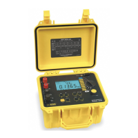
Micro-Ohmmeter Model 6250
31
4.5 Measurement Modes
NOTE: For descriptions of all Fault Indicator (Error) codes, refer to
Chapter 7 - “Troubleshooting” in this manual.
4.5.1 Measurement Safety Warnings
WARNING:
• Never use test leads or measuring wires if there is any evidence
of deterioration (insulation split, burnt, etc).
• Never exceed the safety values indicated in the specications.
• Never connect the unit to a live circuit.
• When the unit is measuring resistance showing a high induc-
tive component (transformers, motors, etc.) after ending the
measurement (with the measurement current cut-o), the unit
then discharges this inductance and displays the
icon for this
entire duration.
• Never disconnect the connection wires before the
icon dis-
appears.
4.5.2 Inductive Resistance Measurement Mode ( )
This mode is intended for performing measurements on inductive devices.
Press the button until the icon shows on the display.
From the Stand-by state, start a test by performing the following:
• Connect the Kelvin probes to the test specimen.
• Press the START/STOP button.
• If the Kelvin probes are incorrectly connected, the display will show
error message “Err 11” (current leads incorrectly connected), or
“Err 12” (voltage leads incorrectly connected). The unit will then
return to the Stand-by state. When the error is corrected, the test
automatically begins again.
w ww . . co m
information@itm.com1.800.561.8187

 Loading...