32
Micro-Ohmmeter Model 6250
• With the current switched o, the residual voltage (V
0
) across the
resistor terminals is measured and displayed. If this voltage level
is too high, “Err 13” will be displayed.
• The current (I) is switched on at the start of a measurement and
remains on continuously until the unit is manually returned to the
Stand-by state by pressing the START/STOP button.
• The voltage across the resistor terminals (V
1
) is measured and
the measurement R = (V
1
- V
0
) / I is displayed.
• All subsequent measurements comprise only a V
n
measurement
as V
0
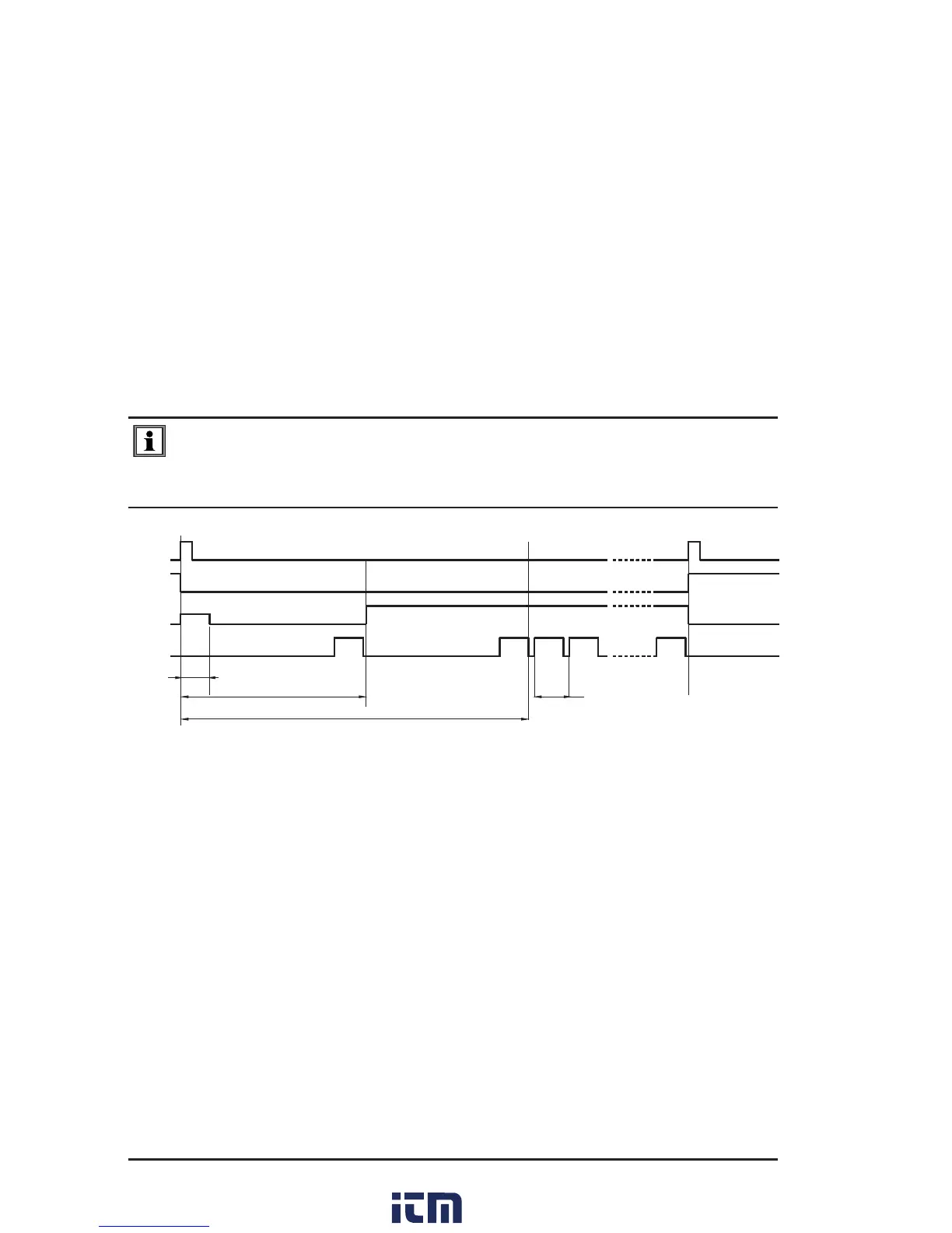
remains in memory. The timing sequence for measurement
is shown in Figure 4-5.
NOTE: After ending the measurement, with the current turned off, the 6250
will discharge the device under test as long as the test leads are connected
to the device.
1
2
3
n
C
0
OPER
MES
I
STBY
640ms
1200ms
120ms
Figure 4-5
C = connection check
0 = residual voltage measurement (stored)
1,2,3…n = successive voltage measurements across the resistor terminals
• The test is stopped by pressing the START/STOP button.
• Store the measurement by rst pressing the MEM button, then
select the object and test location to store the measurement using
the arrow buttons. When the desired location has been selected,
press the MEM button a second time to complete the data storage
process.
w ww . . co m
information@itm.com1.800.561.8187