28
Micro-Ohmmeter Model 6250
4.3 Operating Procedure
WARNING: Before performing the resistance test, verify that the sample
under test is not energized.
4.3.1 Connections and Readings
Clean all surfaces before connecting test leads. Verify a solid connection
between test leads and the sample. Set the range selector switch to the
desired range for the test. If the anticipated resistance is not known, begin
with the highest range (2500Ω) and successively lower the range selection
until adequate resolution is achieved. The START/STOP button will need
to be pressed each time you change ranges. The range selection may be
changed while the instrument is on.
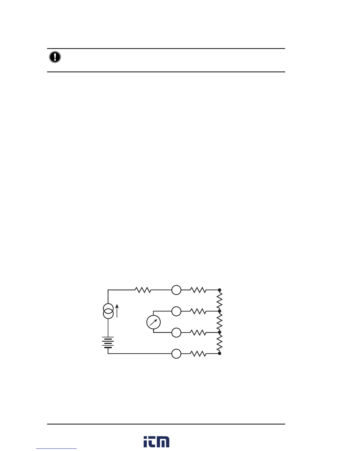
A diagram of the measurement system is shown in Figure 4-2. The
Model 6250 generates a current (I) from the internal voltage source (V).
A voltmeter measures the voltage drop V
x
at the Kelvin probe contact
points to the resistance to be measured (R
x
) and displays the resistance
measurement (R
x
) directly using the formula R
x
= V
x
/ I.
The result is not aected by the other resistances encountered in the cur-
rent loop (R
i
, R
f
, R
c
), as long as the total voltage drop induced across R
x
remains below the voltage supplied by the source which is between 5 to
6V. The maximum admissible lead resistance level is R
f
≈ (V- V
x
) / I. The
use of Kelvin probes helps, as they eliminate the eect of the lead resis-
tance (R
f
).
Ri Rf
Rf
Rf
Rf
C2
P2
P2