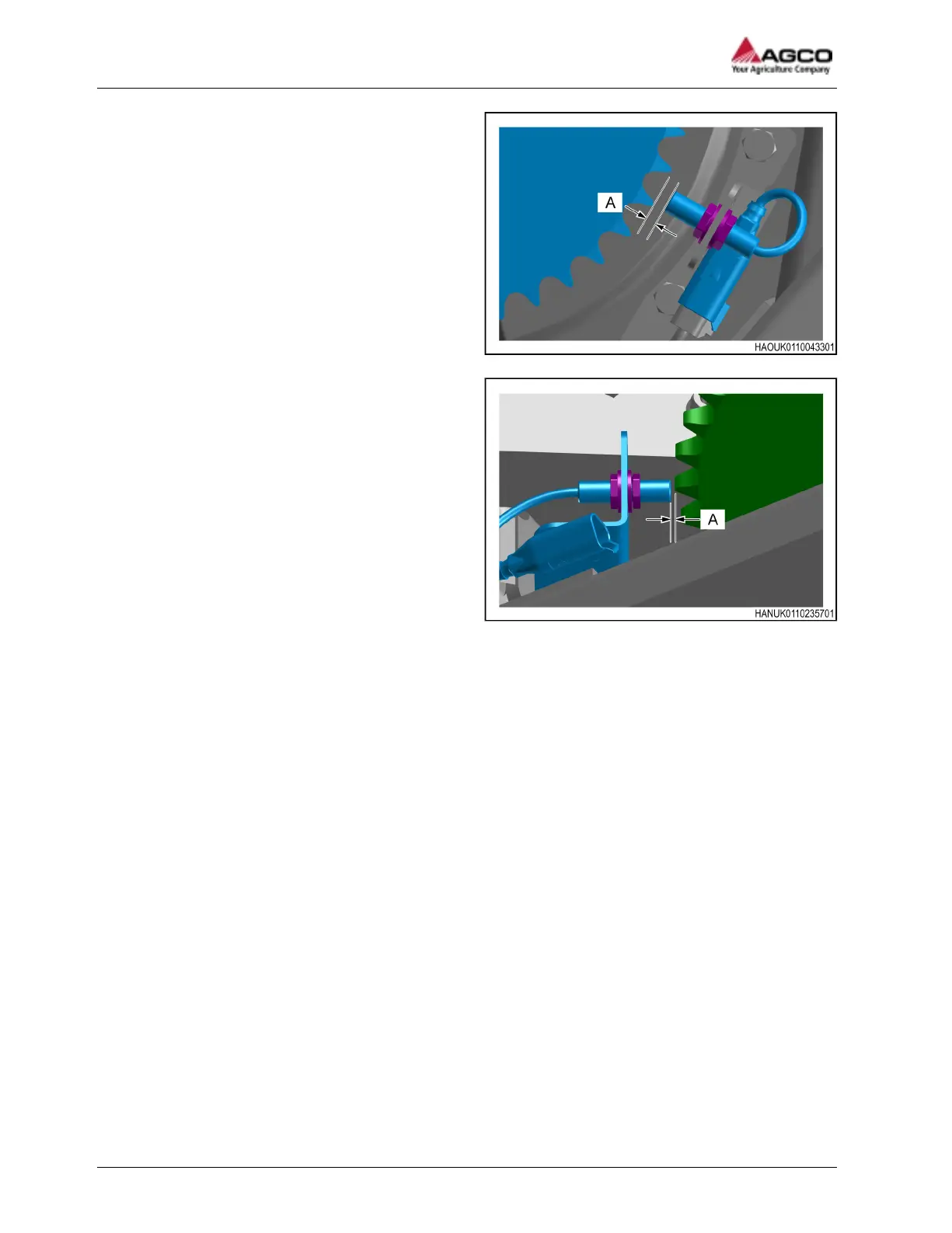
Fig. 13 1840 models
Fig. 14 1844 models
3. Loosen, but do not fully remove the 2 fasteners
on the PTO speed sensor.
4. Use the 2 fasteners to adjust the position of the
PTO speed sensor. The distance (A) must be 1
mm (0 in) to 3 mm (0.1 in).
5. Tighten the fasteners to the approved torque.
6. Turn the machine slowly 1 full turn by hand.
Make sure that the sprocket does not contact or
move out of range of the sensor.
7. Do a check to make sure that the sensor
operates correctly.
IMPORTANT: Make sure that the wiring harness
is connected to the PTO speed sensor.
a) Set the ignition switch to ON.
b) Slowly move the PTO speed sensor
sprocket and examine the LED at the rear
of the sensor.
Result of the procedure
The PTO speed sensor clearance is set correctly when:
• The LED is ON when the sensor is adjacent to a sprocket tooth.
• The LED is OFF when the sensor is not adjacent to a sprocket tooth.
4 Maintenance
60
SimplEbale