32 1260 Infinity II Analytical-Scale & Bio-inert Fraction Collector User Manual
3
Using the Module
Configuration and Operation of the Fraction Collector
Configuration and Operation of the Fraction Collector
Delay Volumes and Delay Calibration
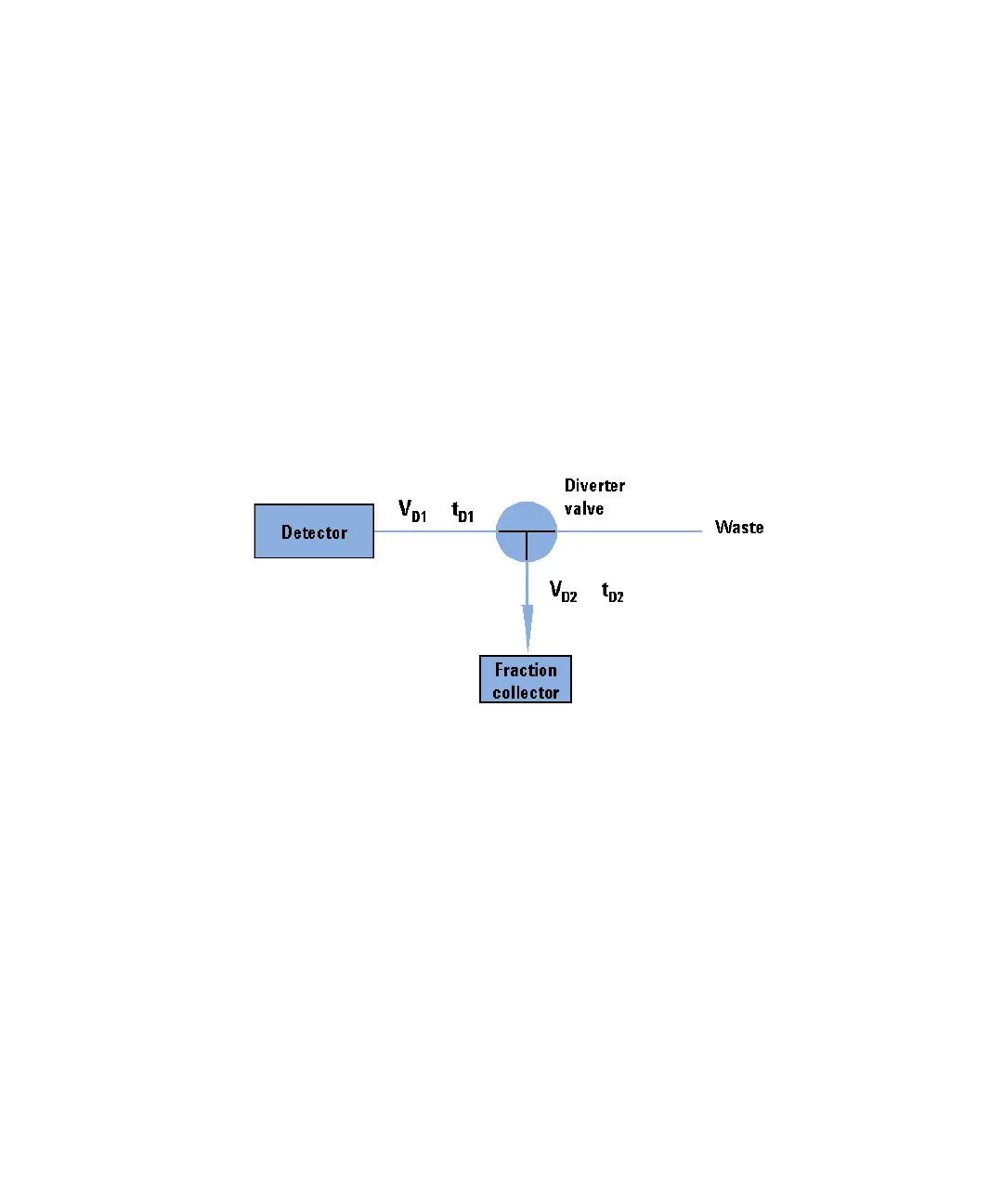
Once software is installed and the fraction collector is ready to be operated,
the fraction delay time needs to be determined. Figure 4 on page 32 shows a
schematic drawing of the flow path between the detector and the fraction
collector with the two delay volumes V
D1
and V
D2
. For peak-based fraction
collection the system delay times t
D1
and t
D2
can be calculated by dividing the
delay volumes by the flow rate.
Figure 4 Delay volumes and delay times
The delay volume V
D2
is a system parameter, it depends on the installed
fraction collector tubing. Delay volume V
D1
, which is specified through the
installed Fraction Collector Tubing Kit, is determined using the Delay Volume
Calibration feature of the Lab Advisor software.
 Loading...