1260 Infinity II Analytical-Scale & Bio-inert Fraction Collector User Manual 33
Using the Module
3
Configuration and Operation of the Fraction Collector
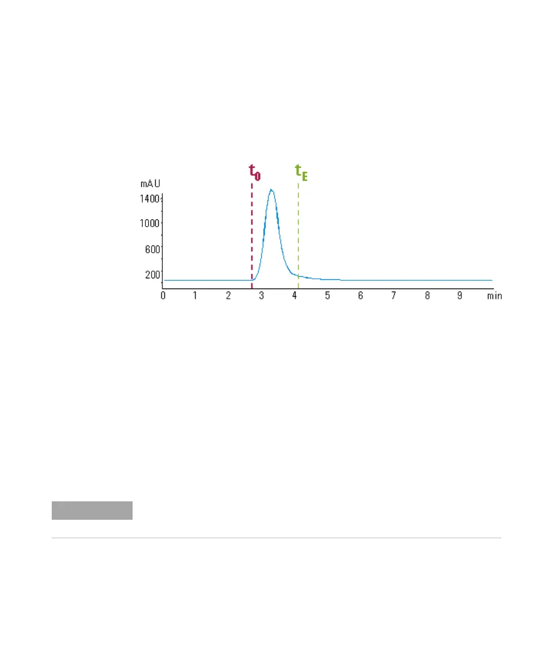
When a peak is detected during a purification run ( Figure 5 on page 33) the
diverter valve is triggered using the following delay time calculations:
• Start of fraction collection: t = t
0
+ t
D1
• End of fraction collection: t = t
E
+ t
D1
+ t
D2
Figure 5 Chromatogram from a UV-detector with peak starting at t
0
and ending at t
E
Performing a Delay Calibration with an UV Detector
1 Place a vial containing the Delay Sensor Calibrant (5190-8223 or
G1946-85020) in position 1 of the autosampler.
2 Remove the installed column and replace for the delay coil or union.
3 Connect a bottle of water to Channel A
4 Open a session of LAB Advisor and connect to the system with the 1260
Infinity II Fraction Collector.
5 Navigate to Service and Diagnostics, select Delay Volume Calibration from the
available tests.
6 Click Run and follow the prompts from the Wizard.
Every Agilent 1260 Infinity detector that is used for triggering fractions has an internal
signal delay caused by filtering the raw data. The signal delay depends on the Peakwidth
setting of the detector and is accounted for when the fraction collector is triggered.
 Loading...