34410A/11A User’s Guide 111
Measurement Tutorial 4
The measurement cycle consists of two parts: a charge phase (shown in
the graph) and a discharge phase. The time–constant during the discharge
phase is longer, due to a 100kW protective resistor in the measurement
path. This time–constant plays an important role in the resultant reading
rate (measurement time).
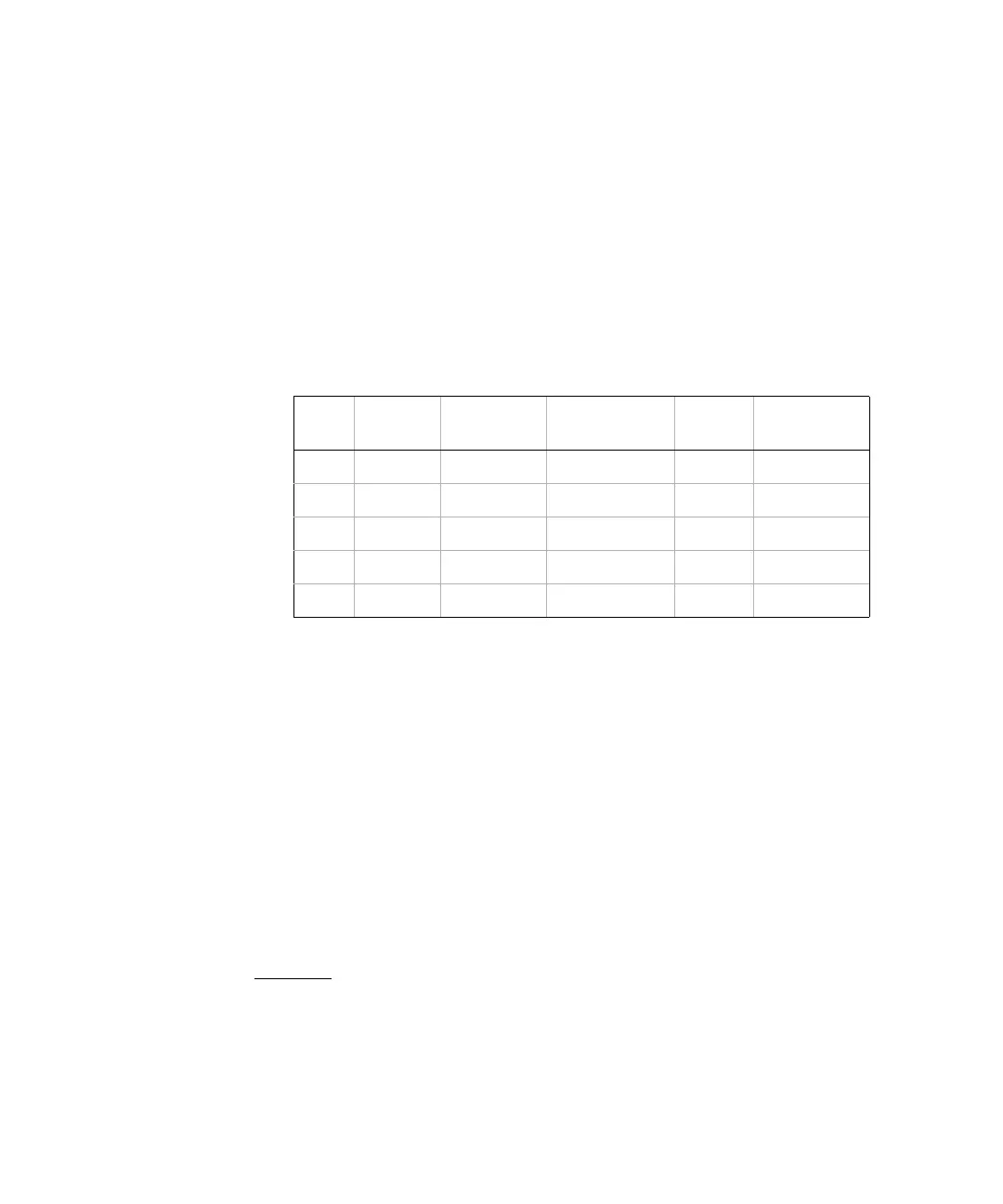
The incremental times, or “sample times”, as well as the width of the
“short apertures”, vary by range, in order to minimize noise and increase
reading accuracy. The following table lists the current amplitude, peak
voltage and average dc voltage developed across the capacitor during the
measurement.
These values all vary by range. Control of the peak voltage across the
capacitor is important in some cases, such as when measuring larger
electrolytic capacitors.
The values of capacitance and loss resistance measured with the
multimeter may differ from the values measured using an LCR meter. This
is to be expected, since this is esentially a dc measurement method, while
LCR measurement uses applied frequencies anywhere from 100 Hz to 100
kHz. In most cases, neither method measures the capacitor at its exact
frequency of application.
The multimeter will measure capacitance over a range from 1nF to 10mF.
Voltage developed across the capacitor being measured is limited to less
than 10V. The multimeter’s measurement accuracy is 0.4% of the reading,
+ 0.1% of the range in use (except for the 1nF range, for which the
accuracy is 0.5% of the reading, + 0.5% of the range).
Example:
For a 5 nF capacitor, measured using the 10 nF range, the
accuracy will be (0.4%)(5 nF) + (0.1%)(10 nF) = 30 pF total error possible.
For the best accuracy, take a zero null measurement with open probes, to
null out the test lead capacitance, before connecting the probes across the
capacitor to be measured.
Range Current
Source
Reading Rate
at full scale
Reading Rate @
10% of full scale
Applied
Voltage
Approx. dc bias
@ full scale
1 nF 500nA 5/second 12/second 5V 2V
10 nF 1mA 5/second 24/second 5V 2V
100 nF 10mA 5/second 26/second 4V 2V
1 mF10mA 2/second 18/second 1.5V 1V
10 mF100mA 0.3/second 2.5/second 1.5V 1V
 Loading...


