4349B
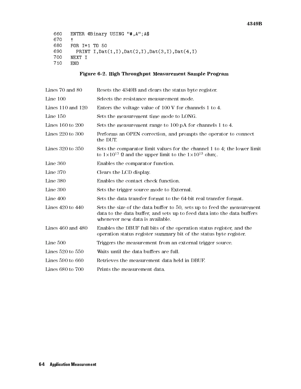
660
ENTER @Binary
USING "#,A";A$
670
!
680
FOR I=1
TO
50
690
PRINT I,Dat(1,I),Dat(2,I),Dat(3,I),Dat(4,I)
700
NEXT I
710
END
Figure
6-2.
High
Throughput
Measurement
Sample
Program
Lines
70
and
80
Resets
the 4349B
and clears
the status
byte register
.
Line
100
Selects
the
resistance
measurement mode
.
Lines
110
and
120
Enters
the
voltage
value of
100 V
for channels
1
to
4.
Line
150
Sets
the measurement
time mode
to LONG.
Lines
160
to
200 Sets
the measurement
range to
100
pA
for
channels
1
to
4.
Lines
220
to
300
P
erforms an
OPEN correction,
and
prompts
the
operator
to
connect
the
DUT
.
Lines
320
to
350
Sets
the
comparator
limit
values
for
the
channel
1
to
4;
the
lower limit
to
1
2
10
12
and
the
upper
limit
to
the
1
2
10
13
ohm;.
Line
360
Enables
the
comparator
function.
Line
370
Clears
the
LCD
display
.
Line
380
Enables
the
contact
check
function.
Line
390
Sets
the
trigger
source
mode
to
External.
Line
400
Sets
the
data
transfer
format
to
the
64-bit
real
transfer
format.
Lines
420
to
440
Sets
the
size
of
the
data
buer
to
50,
sets
up to
feed
the
measurement
data
to
the
data
buer
,
and sets
up to
feed
data
into
the
data
buers
whenever
new
data
is
available
.
Lines
460
and
480
Enables the
DBUF full
bits of
the operation
status
register
,
and
the
operation
status
register
summary
bit
of
the status
byte register
.
Line 500
Triggers the
measurement
from
an
external
trigger
source
.
Lines 520
to 550
Waits
until
the
data
buers
are
full.
Lines 590
to 660
Retrieves the
measurement data
held in
DBUF
.
Lines 680 to 700
Prints the measurement data.
6-4 Application Measurement