4349B
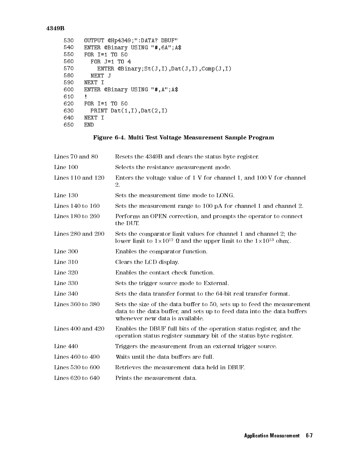
530
OUTPUT @Hp4349;":DATA?
DBUF"
540
ENTER @Binary
USING
"#,6A";A$
550
FOR I=1
TO
50
560
FOR J=1
TO
4
570
ENTER @Binary;St(J,I),Dat(J,I),Comp(J,I)
580
NEXT J
590
NEXT
I
600
ENTER
@Binary
USING
"#,A";A$
610
!
620
FOR
I=1
TO
50
630
PRINT
Dat(1,I),Dat(2,I)
640
NEXT
I
650
END
Figure
6-4.
Multi
T
est
Voltage
Measurement Sample
Program
Lines
70
and
80
Resets
the 4349B
and clears
the
status
byte
register
.
Line
100
Selects
the
resistance
measurement
mode
.
Lines
110
and
120
Enters
the
voltage
value
of
1
V
for
channel
1,
and
100
Vfor
channel
2.
Line
130
Sets
the
measurement
time
mode
to
LONG.
Lines
140
to
160
Sets
the
measurement
range
to
100
pA
for
channel
1
and
channel
2.
Lines
180
to
260
P
erforms
an
OPEN
correction,
and
prompts
the
operator to
connect
the
DUT
.
Lines
280
and
290
Sets
the
comparator
limit
values
for
channel
1
and
channel 2;
the
lower
limit
to
1
2
10
12
and
the
upper
limit
to
the
1
2
10
13
ohm;.
Line
300
Enables
the
comparator
function.
Line
310
Clears
the
LCD
display
.
Line
320
Enables
the
contact check
function.
Line
330
Sets
the
trigger
source
mode to
External.
Line 340
Sets the
data transfer
format
to
the
64-bit
real
transfer
format.
Lines 360
to 380
Sets the
size
of
the
data
buer
to
50,
sets
up
to
feed
the
measurement
data to
the data
buer,
and sets
up to
feed
data
into
the
data
buers
whenever
new
data
is
available
.
Lines 400 and 420
Enables the DBUF full bits of the operation status register
, and the
operation
status register summary bit of the status byte register
.
Line 440
Triggers the measurement from an external trigger source
.
Lines 460 to
490 Waits until the data buers are full.
Lines 530 to 600
Retrieves the measurement data held in DBUF
.
Lines 620 to 640 Prints the measurement data.
Application Measurement 6-7