4349B
Front
P
anel
This
section
gives
a
guided
tour
of
the
front
panel.
F
or
a
detailed
description
of each
key's function,
see Chapter
3.
A
description
starting
with
(Shift)
is the
secondary function
of the
key,
which is
available by
pressing
the
BLUE
shift
key
(see
31).
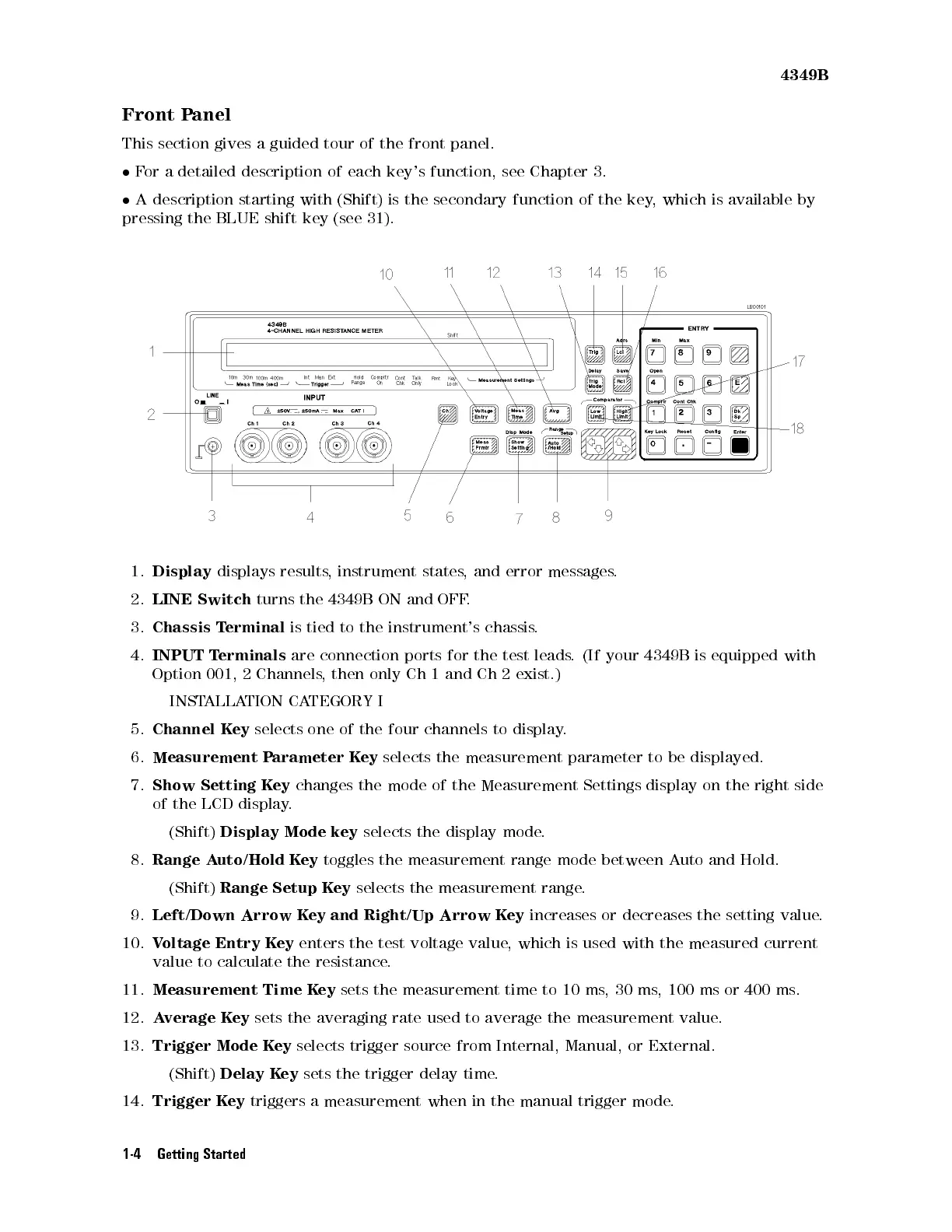
1.
Display
displays
results
,
instrument
states
,
and
error
messages
.
2.
LINE
Switch
turns
the
4349B
ON
and
OFF
.
3.
Chassis
T
erminal
is
tied
to
the
instrument's
chassis
.
4.
INPUT
T
erminals
are
connection
ports
for
the
test
leads
.
(If
your
4349B
is
equipped with
Option
001,
2
Channels
,
then
only
Ch
1
and
Ch
2
exist.)
INST
ALLA
TION
CA
TEGORY
I
5.
Channel
K
ey
selects
one
of the
four channels
to display
.
6.
Measurement
P
arameter
K
ey
selects
the
measurement parameter
to be
displayed.
7.
Show
Setting
K
ey
changes
the
mode
of the
Measurement Settings
display on
the right
side
of the
LCD display
.
(Shift)
Display
Mode
key
selects
the
display
mode
.
8.
Range A
uto/Hold K
ey
toggles the measurement range mode between A
uto and Hold.
(Shift)
Range Setup K
ey
selects the measurement range
.
9.
Left/Down Arrow K
ey and
Right/Up Arrow K
ey
increases or decreases the setting value
.
10.
Voltage Entry K
ey
enters
the test voltage value
, which is used with the measured current
value to calculate the resistance
.
11.
Measurement Time K
ey
sets the measurement time to 10 ms
,30ms,100ms
or 400 ms.
12.
Average Key
sets the averaging rate used to average the measurement value.
13.
Trigger Mode Key
selects trigger source from Internal, Manual, or External.
(Shift)
Delay Key
sets the trigger delay time.
14.
Trigger Key
triggers a measurement when in the manual trigger mode.
1-4 Getting Started