Setting Up the Oscilloscope
To connect a printer
1-23
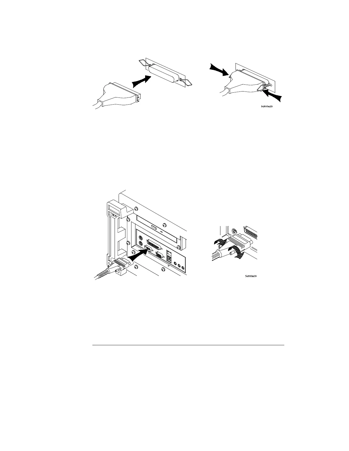
Figure 1-16
Attaching the Larger “D” Connector
3 Set the printer configuration to use the “Centronics” or “Parallel”
interface, if necessary. See the documentation for your printer.
4 Go to “To install the printer software” in Chapter 3.
5 Connect the 9-pin “D” connector of the serial printer cable to the serial
output port on the rear panel of the oscilloscope. Tighten the
thumbscrews to secure the cable.
Figure 1-17
Attaching the 9-pin “D” Connector
Port on Printer
 Loading...


