Electronics 8
Troubleshooting and Maintenance Manual 173
Main boards
Two main boards are mounted on the outer side of the electronics module. The
boards are identical except that main board 1 carries the log amplifier for the
detector signal and the EMV power supply.
The main boards are mounted on the outer side of the electronics module.
They perform these functions:
• Receive and decode digital instructions from the LAN/MS control card.
• Send digital information to the LAN/MS control card.
• Generate voltages for the ion source lenses and the collision cell.
• Generate control signals for filament selection, filament emission current,
and electron energy. Generate control signals for quadrupole RF drive,
quad frequency adjustment, DC polarity selection, and all detector voltages.
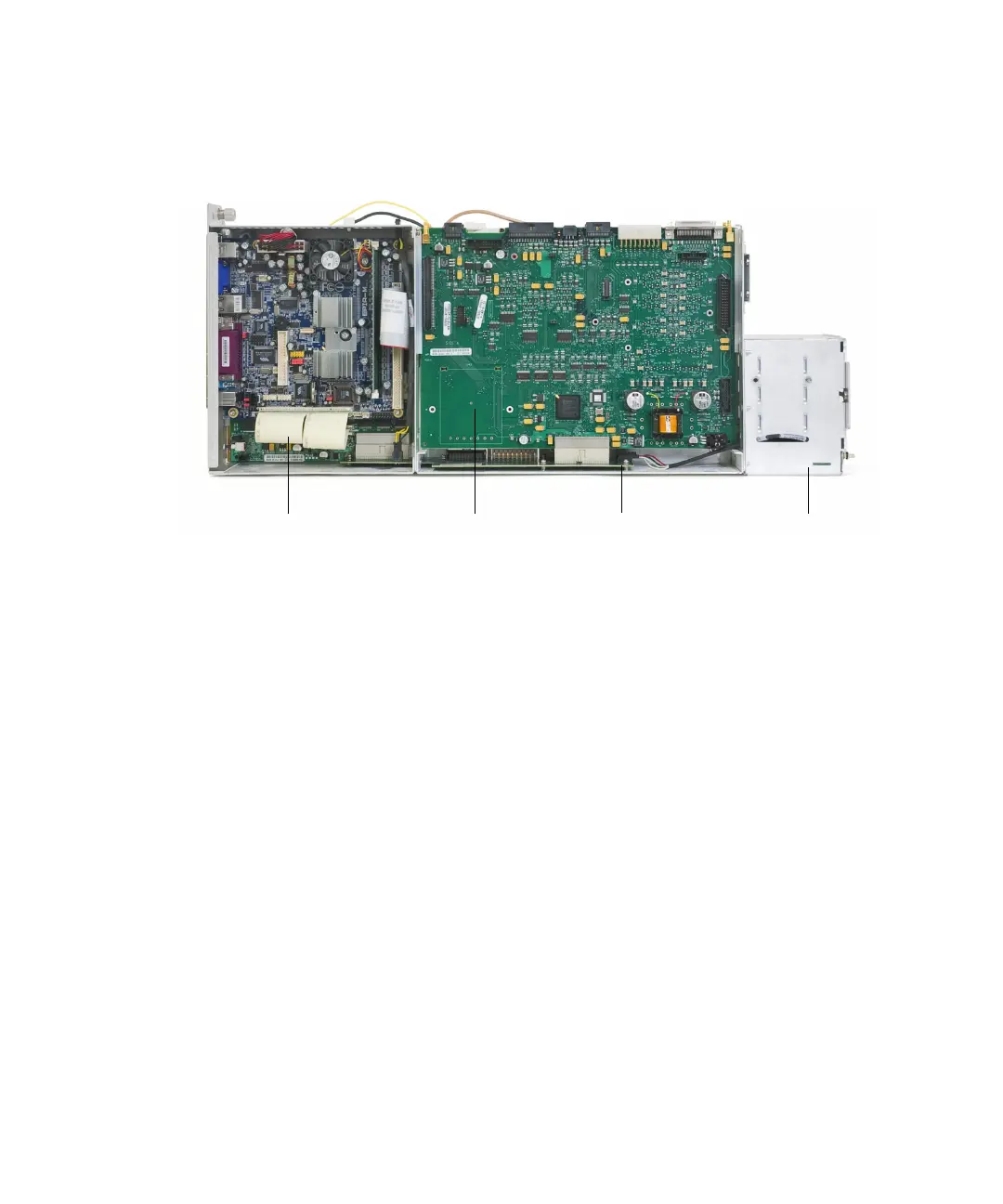
Figure 41 Electronics module, side 2
LAN board
Main board 2
(main board 1 is behind it)
Bus board
Power switch board
 Loading...