Chapter 6 6-17
Digital Control Troubleshooting
Run the Internal Diagnostic Tests
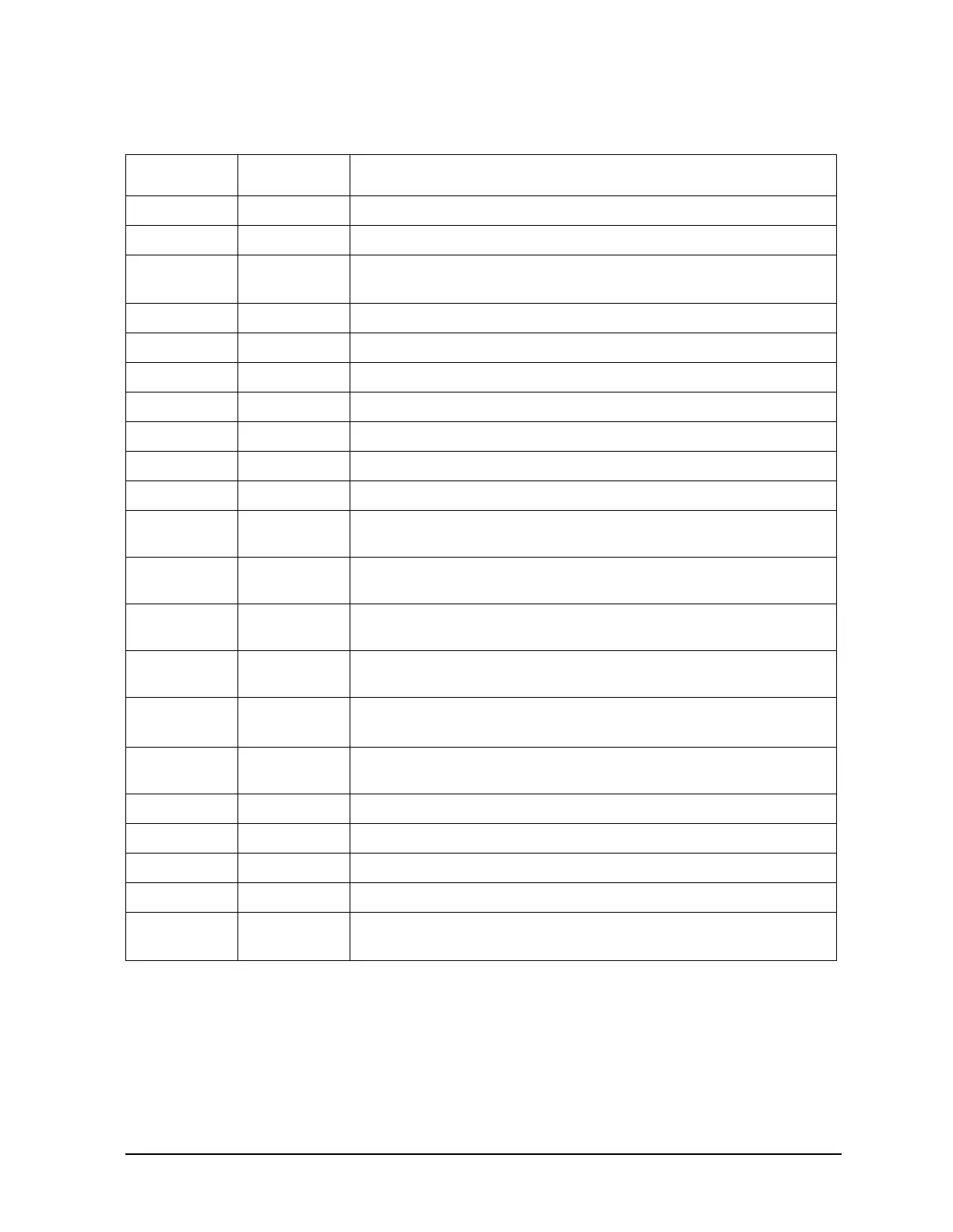
Table 6-2 Internal Diagnostic Test with Commentary
Test
Sequence
a
Probable Failed Assemblies
b
: Comments and Troubleshooting Hints
0 All Int — - — : Executes tests 3-11, 13-16, 20.
1 Preset — - — : Executes tests 2-11, 14-16. Runs at power-on or preset.
2 ROM P,AI
A9: Repeats on fail; refer to
“CPU Troubleshooting (A9)” on page 6-5
to replace ROM or A9.
3 CMOS RAM P,AI A9: Replace A9.
4 Main DRAM P,AI A9: Repeats on fail; replace A9.
5 DSP Wr/Rd P,AI A9: Replace A9.
6 DSP RAM P,AI A9: Replace A9.
7 DSP ALU P,AI A9: Replace A9.
8 DSP Intrpt P,AI A9/A10: Remove A10, rerun test. If fail, replace A9. If pass, replace A10.
9 DIF Control P,AI A9/A10: Most likely A9 assembly.
10 DIF
Counter
P,AI A10/A9/A12: Check analog bus node 17 for 1 MHz. If correct, A12 is
verified; suspect A10.
11 DSP
Control
P,AI A10/A9: Most likely A10.
12 Fr Pan
Wr/Rd
— - A2/A1/A9: Run test 23. If fail, replace A2. If pass, problem is on bus
between A9 and A2 or on A9 assembly.
13 Rear Panel AI A16/A9: Disconnect A16, and check A9J2 pin 48 for 4 MHz clock signal.
If OK, replace A16. If not, replace A9.
14 Post-reg P,AI
A15/A8/Destination assembly: See
Chapter 5 , “Power Supply
Troubleshooting.”
15 Frac-N
Cont
P,AI A14: Replace A14.
16 Sweep Trig P,AI A14,A10: Most likely A14.
17 ADC Lin — - A10: Replace A10.
18 ADC Ofs — - A10: Replace A10.
19 ABUS Test — - A10: Replace A10.
20 FN Count AI A14/A13/A10: Most likely A14 or A13, as previous tests check A10. See
Chapter 7 , “Source Troubleshooting.”
a. P = Part of “Preset” sequence; AI = part of “All Internal” sequence
b. In decreasing order of probability.

 Loading...


