Chapter 12 12-27
Theory of Operation
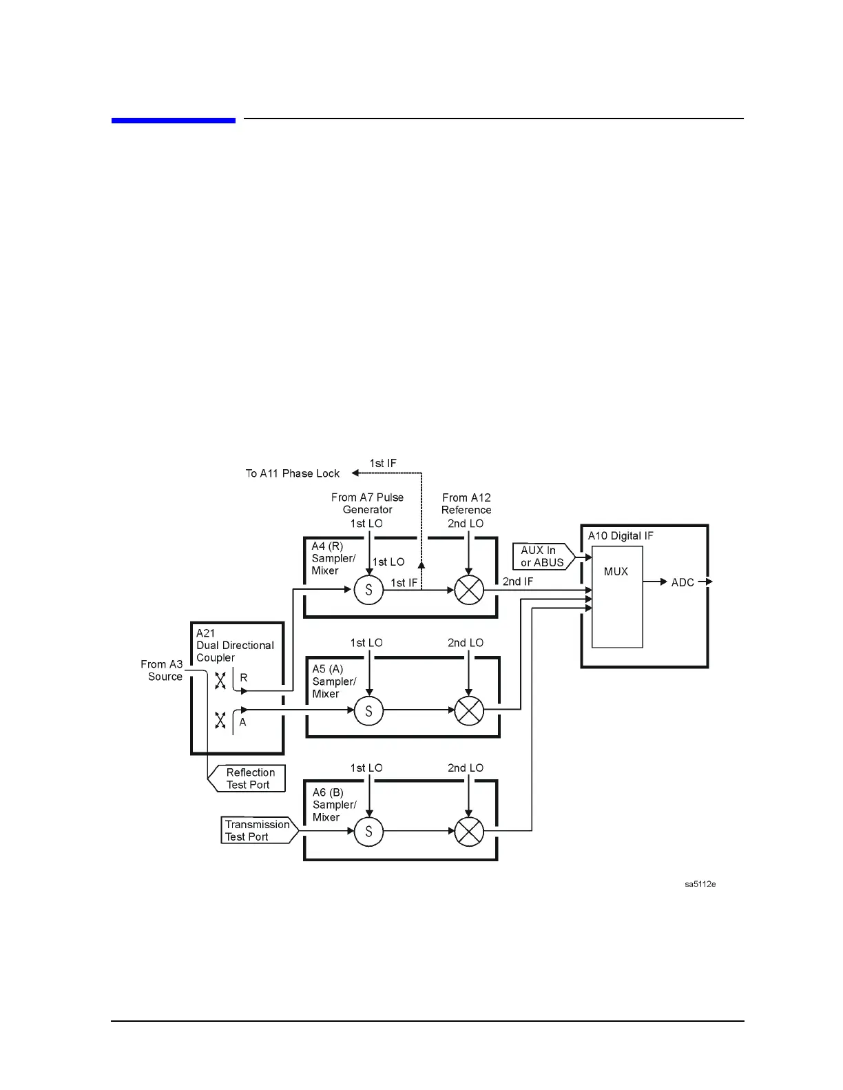
Receiver Theory
Receiver Theory
The receiver functional group consists of the following assemblies:
• A4 sampler/mixer
• A5 sampler/mixer
• A6 sampler/mixer
•A10 digital IF
These assemblies combine with the A9 CPU (described in “Digital Control Theory” on
page 12-9) to measure and process input signals into digital information for display on the
analyzer. Figure 12-12 through Figure 12-14 are simplified block diagrams of the receiver
functional group. The A12 reference assembly is also included in the illustration to show
how the 2nd LO signal is derived.
Figure 12-12 Receiver Functional Group, 8753ET without Option 004

 Loading...


