7-24 Chapter 7
Source Troubleshooting
Phase Lock Error
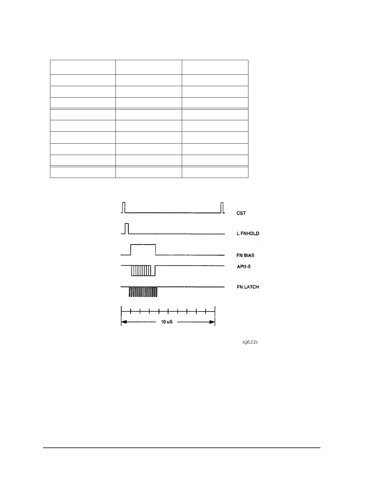
Figure 7-21 A14 Generated Digital Control Signals
H MB Line This signal is active during the 16 MHz to 31 MHz sweep. The upper trace of
Figure 7-22 shows relative inactivity of this signal during preset condition. The lower trace
shows its status during a 16 MHz to 31 MHz sweep with inactivity during retrace only.
Table 7-6 A14-to-A13 Digital Control Signal Locations
Mnemonic A13 Location A14 Location
CST none TP3
L FNHOLD P2-2 P2-2
FNBIAS P2-5 P2-5
API1 P2-32 P2-32
API2 P2-3 P2-3
API3 P2-34 P2-34
API4 P2-4 P2-4
API5 P2-35 P2-35
FN LATCH P1-28 P1-58

 Loading...


