Pulse Width Modulation (PWM)
Pulse Width Modulation (PWM)
This section discusses PWM, which stands for pulse-width modulation. PWM is only available for the Pulse waveform,
and the pulse width varies according to the modulating signal. The amount by which the pulse width varies is called the
width deviation, and it can be specified as a percentage of the waveform period (that is, duty cycle) or in units of time.
For example, if you specify a pulse with 20% duty cycle and then enable PWM with a 5% deviation, the duty cycle
varies from 15% to 25% under control of the modulating signal.
The instrument accepts an internal or external modulation source.
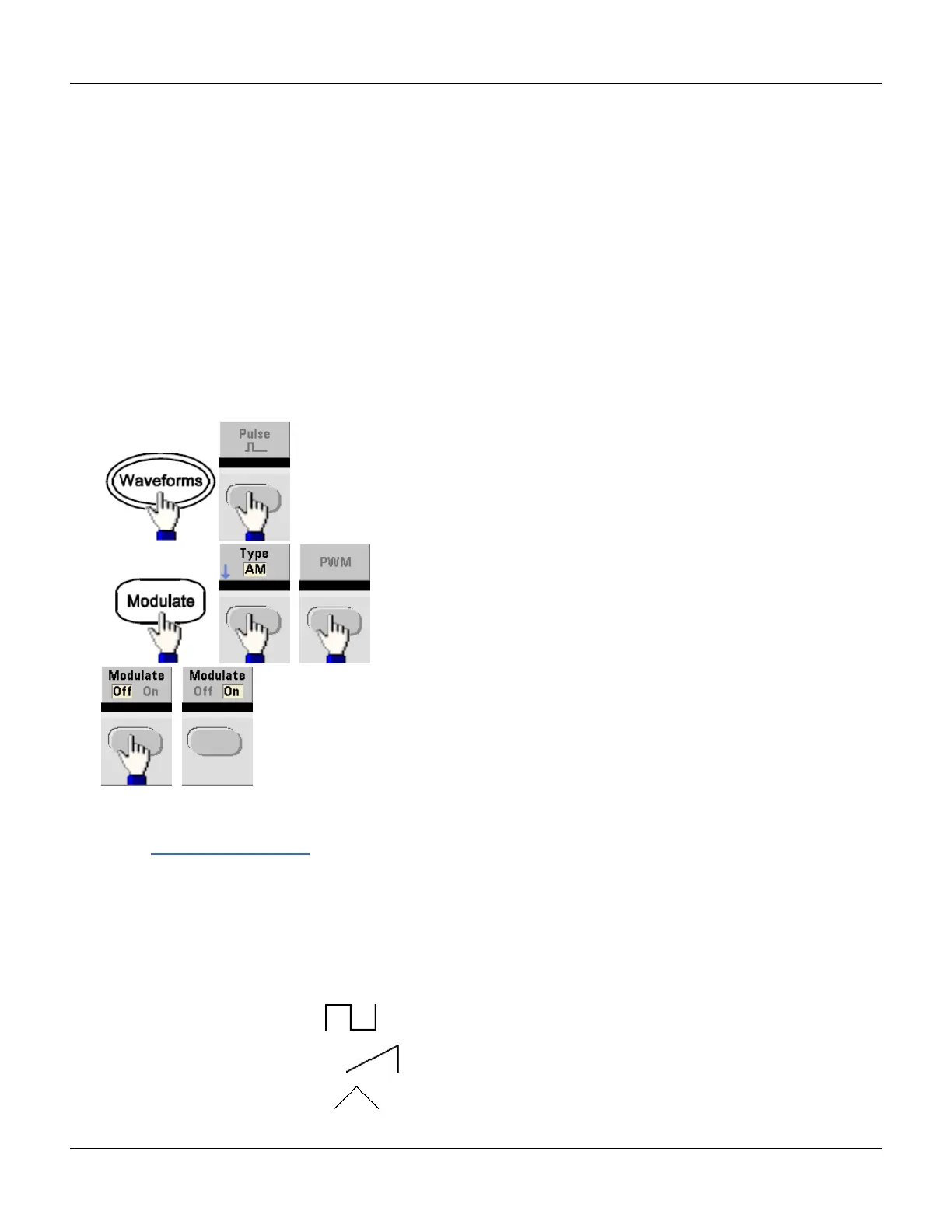
To Select PWM Modulation
l You cannot enable PWM when sweep or burst is enabled.
l To avoid multiple waveform changes, enable modulation after configuring the other modulation parameters.
l Front Panel:
The waveform is output using the present carrier and modulating waveform settings.
l SCPI: PWM:STATe {OFF|ON}
Modulating Waveform Shape
The instrument accepts an internal or external modulation source.
l The modulating waveform shape (internal source) may be:
l Sine wave
l
Square with 50% duty cycle
l
UpRamp with 100% symmetry
l
Triangle with 50% symmetry
Agilent 33500 Series Operating and Service Guide 83

 Loading...


