Output Configuration
Output Configuration
This section describes output channel configuration. Many commands associated with output configuration start with
SOURce1: or SOURce2: to indicate a certain channel. If omitted, the default is channel 1. For example, VOLT 2.5 sets
the output on channel 1 to 2.5 V, and SOUR2:VOLT 2.5 does the same for channel 2.
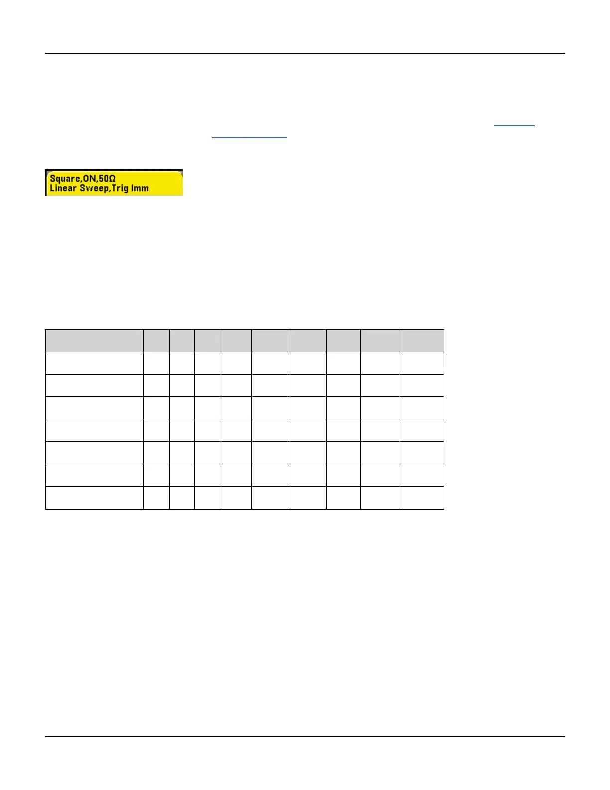
The instrument's display includes a "tab" for each channel that summarizes various aspects of each channel's output
configuration:
On a two-channel instrument, the tab for channel 1 will be yellow, and the tab for channel 2 will be green.
Output Function
The instrument includes eight standard waveforms: sine, square, ramp, pulse, triangle, noise, PRBS (pseudo-random
binary sequence), and DC. There are also nine built-in arbitrary waveforms, and you can create custom waveforms
with the embedded waveform editor.
The table below shows which functions are allowed (•) with modulation, sweep, and burst. Selecting a function that is
not allowed with a modulation or mode disables the modulation or mode.
Carrier AM FM PM FSK BPSK PWM Sum Burst Sweep
Sine and Square • • • • • • • •
Pulse • • • • • • • • •
Triangle and Ramp • • • • • • • •
Gaussian Noise • • •
a
PRBS • • • • •
Arbitrary Waveform • • •
b
•
b
• • •
Sequence • •
(a) Gated burst only
(b) Applies to sample clock, not whole waveform
l Frequency Limitations: Changing functions may change the frequency to meet the new function's frequency lim-
its.
l Amplitude Limitations: When the output units are Vrms or dBm, changing functions may lower the amplitude to
the maximum for the new function due to variation in waveform shapes. For example, a 5 Vrms square wave (into
50 Ω) changed to a sine will decrease to 3.536 Vrms (sine’s upper limit).
l Amplitude and offset cannot combine to exceed the instrument’s capability. The one you set last may be changed
to stay within limits.
l You may protect a device under test (DUT) by specifying upper and lower output voltage limits.
l Front Panel:
56 Agilent 33500 Series Operating and Service Guide

 Loading...


